
LED light matrix equipped with impulse means

a technology of impulse means and led light, which is applied in the direction of material analysis by optical means, instruments, lighting and heating apparatus, etc., can solve the problems of inability to extend images, too much light within a close range, and too little light, so as to improve imaging conditions and eliminate fire risk

Active Publication Date: 2012-06-12
METSO AUTOMATION OY
View PDF14 Cites 2 Cited by
  • Summary
  • Abstract
  • Description
  • Claims
  • Application Information

AI Technical Summary

Benefits of technology

The solution enhances imaging efficiency, reduces fire risks, and extends the effective imaging area within paper machines by optimizing light distribution and reducing glare, while maintaining low power consumption and heat generation.

Problems solved by technology

In particular, a paper machine has a numerous amount of objects to be monitored by video cameras where both imaging and illuminating are arranged from outside the web since imaging equipment cannot be set on top of the web.
Then there is even too much light within a close range and too little light at a certain distance from the web edge.
The effective imaging area remains rather small and often the image cannot be extended even near to the machine center point.
Still commonly used in the paper machine environment are halogen lights and metal halide lights, which have high power consumption, whereby the heat generation is also problematically great.
Hot lamps can even cause a fire when waste accumulates on top of the lamp.
However, so far the use of LED light matrices has been rather limited, although they reduce substantially the power consumption and heat generation.
In any case, an oblique illumination angle is an obvious problem also when using LED light fixtures.
With increasing illumination efficiency, their glare effect usually increases, which impairs working conditions.

Method used


Image

  • LED light matrix equipped with impulse means
  • LED light matrix equipped with impulse means
  • LED light matrix equipped with impulse means

Examples


Embodiment Construction

[0011]The invention is described below by means of examples and enclosed drawings.

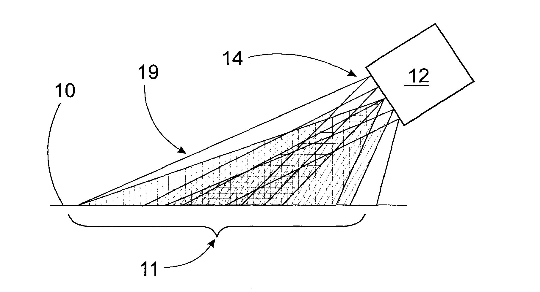
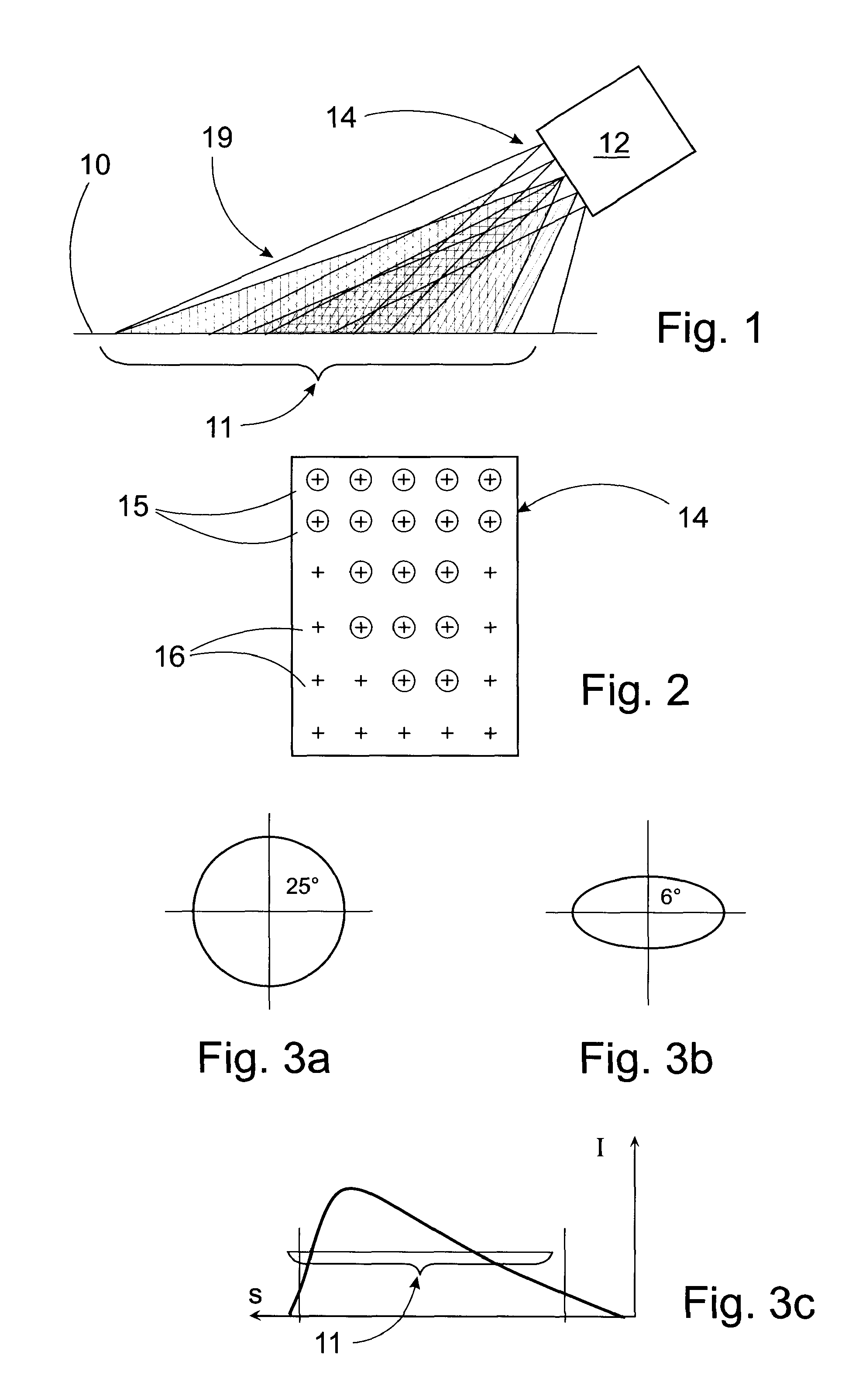
[0012]FIG. 1 is a side view of an illumination geometry,

[0013]FIG. 2 is a schematic view of a LED light matrix according to the invention,

[0014]FIGS. 3a and 3b illustrate two different types of radiation beams,

[0015]FIG. 3c illustrates the intensity distribution of illumination in a selected area,

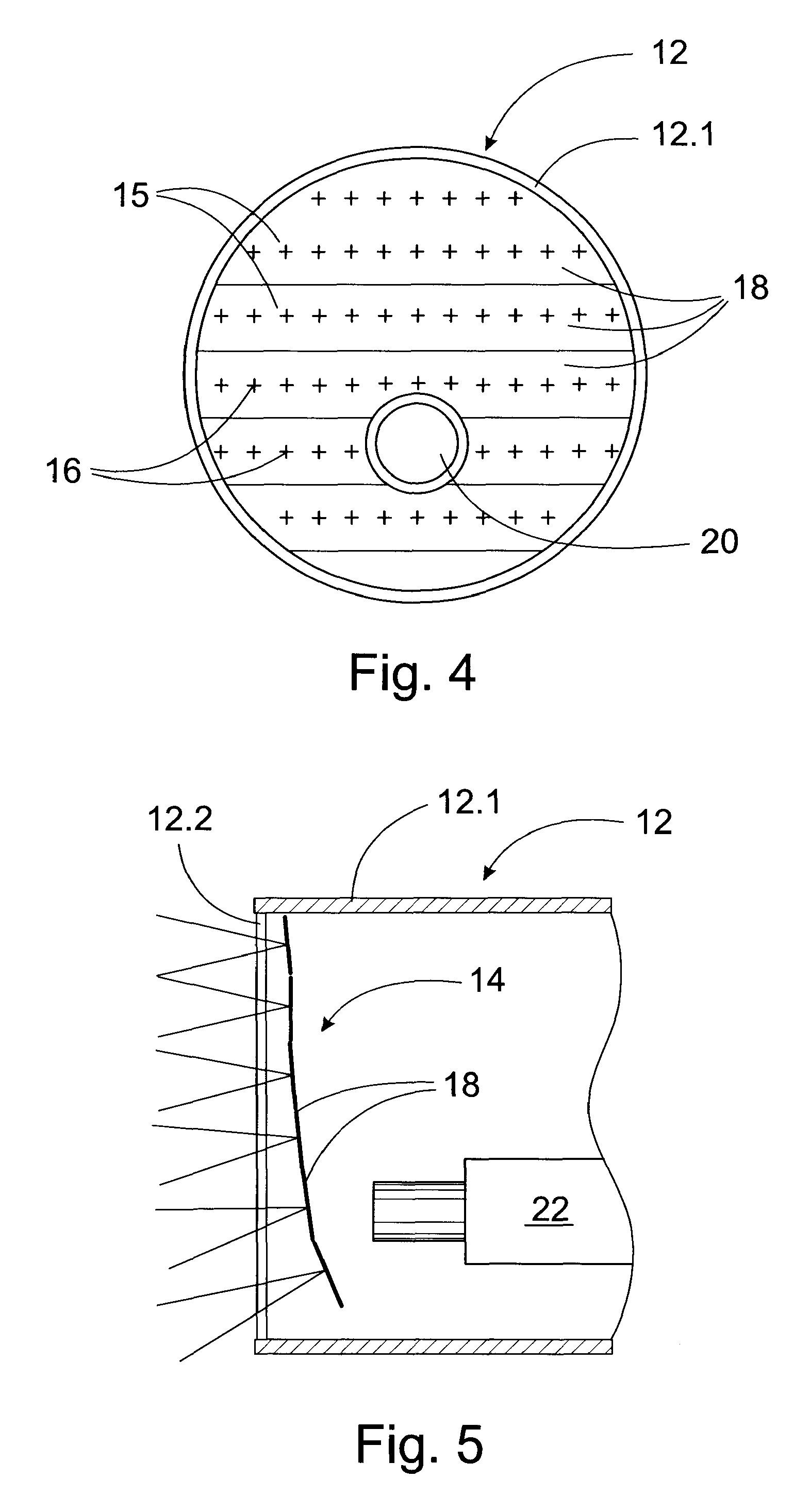
[0016]FIG. 4 is a front view of a camera illumination unit,

[0017]FIG. 5 is a lateral cut view of the unit of FIG. 4,

[0018]FIG. 6 is an axonometric view of another camera illumination unit,

[0019]FIG. 7 is a direct front view of the unit of FIG. 7,

[0020]FIG. 8 illustrates the mutual timing of a camera shutter and a LED light impulse.

[0021]In the example of FIG. 1, a light matrix 14 in a light unit 12 illuminates an object 10 (a paper machine web, for example) in a selected area 11. The web travels orthogonally to the imaging plane the selected area 11 being thus a narrow band extending from the web edge toward t...


PUM


Abstract

The invention relates to a LED light matrix (14) equipped with impulse means for illuminating a moving object (10) in a selected area (11) from an oblique direction for video imaging, said LED light matrix (14) including a group of LEDs (15, 16) each equipped with optics for focusing the light produced by the LED, and with the group being located substantially obliquely relative to the object to be illuminated. Separate LEDs (15, 16) of the LED light matrix (14) are so oriented that the intensity distribution of illumination in the selected area (11) is weighted proportionally to the distance.

Description

BACKGROUND ART[0001]The invention relates to a LED light matrix equipped with impulse means for illuminating a moving object in a selected area from an oblique direction for video imaging, said LED light matrix including a group of LEDs each equipped with optics for focusing the light produced by the LED, and the group being located substantially obliquely relative to the object to be illuminated.PRIOR ART TECHNOLOGY[0002]In particular, a paper machine has a numerous amount of objects to be monitored by video cameras where both imaging and illuminating are arranged from outside the web since imaging equipment cannot be set on top of the web. Imaging set outside the web as well as illumination always take place obliquely relative to the web. Then there is even too much light within a close range and too little light at a certain distance from the web edge. The efficiency of focused illumination reduces proportionally to the square of the distance, but the intensity of light leaving t...

Claims


Application Information

Patent Timeline
Patent Type & Authority Patents(United States)
IPC IPC(8): G03B15/02F21Y101/00
CPCG01N21/8806G01N21/8901F21V14/00G01N21/86H01L33/00
Inventor RUUSKA, HANNU
Owner METSO AUTOMATION OY
Learn More