
Driving power control apparatus for four wheel drive vehicle

a technology of power control apparatus and four-wheel drive, which is applied in the direction of electric devices, process and machine control, instruments, etc., can solve the problems of affecting the total the upper limit naturally arises, and the difficulty of maintaining the high efficiency of the electric motor device as a whole, so as to improve the overall efficiency of the motor, improve the mileage, and widen the output range

Active Publication Date: 2012-06-05
TOYOTA JIDOSHA KK +1
View PDF28 Cites 14 Cited by
  • Summary
  • Abstract
  • Description
  • Claims
  • Application Information

AI Technical Summary

Benefits of technology

[0016]The present driving power control apparatus for a four wheel drive vehicle has the first and second motors configured to have different rated outputs, respectively, and also be drivable at different rotational speeds, respectively, for a specific vehicular speed. Accordingly, in their respective characteristics in efficiency with respect to torque and vehicular speed, the motors exhibit high efficiency in different ranges, respectively. Accordingly, the motors' total efficiency can be held high across a high-to-low, wide output range by appropriately determining an allocation of a drive torque between the first and second motors so as to increase the motors' total efficiency in accordance with the motors' total, required drive torque and vehicular speed. As a result the four wheel drive vehicle can be improved in mileage.
[0035]In accordance with the present invention a four wheel drive vehicle having as a motive power source a plurality of motors configured to have different rated outputs and be drivable at different rotational speeds for a specific vehicular speed can hold the motors' total efficiency high across a high to low, wide output range. As a result the four wheel drive vehicle can achieve improved mileage.

Problems solved by technology

For example, in the FIG. 14 efficiency map, the first and second motors are both less efficient in a low output range, and it is considered difficult that the electric motor device as a whole maintains high efficiency until it reaches the low output range.
As such, an upper limit naturally arises to the motors' total efficiency that can be implemented.

Method used


Image

  • Driving power control apparatus for four wheel drive vehicle
  • Driving power control apparatus for four wheel drive vehicle
  • Driving power control apparatus for four wheel drive vehicle

Examples


Embodiment Construction

[0050]Hereinafter reference will be made to the drawings to describe the present invention in embodiments. In the figures, identical or corresponding components are identically denoted and will not be described repeatedly in detail.

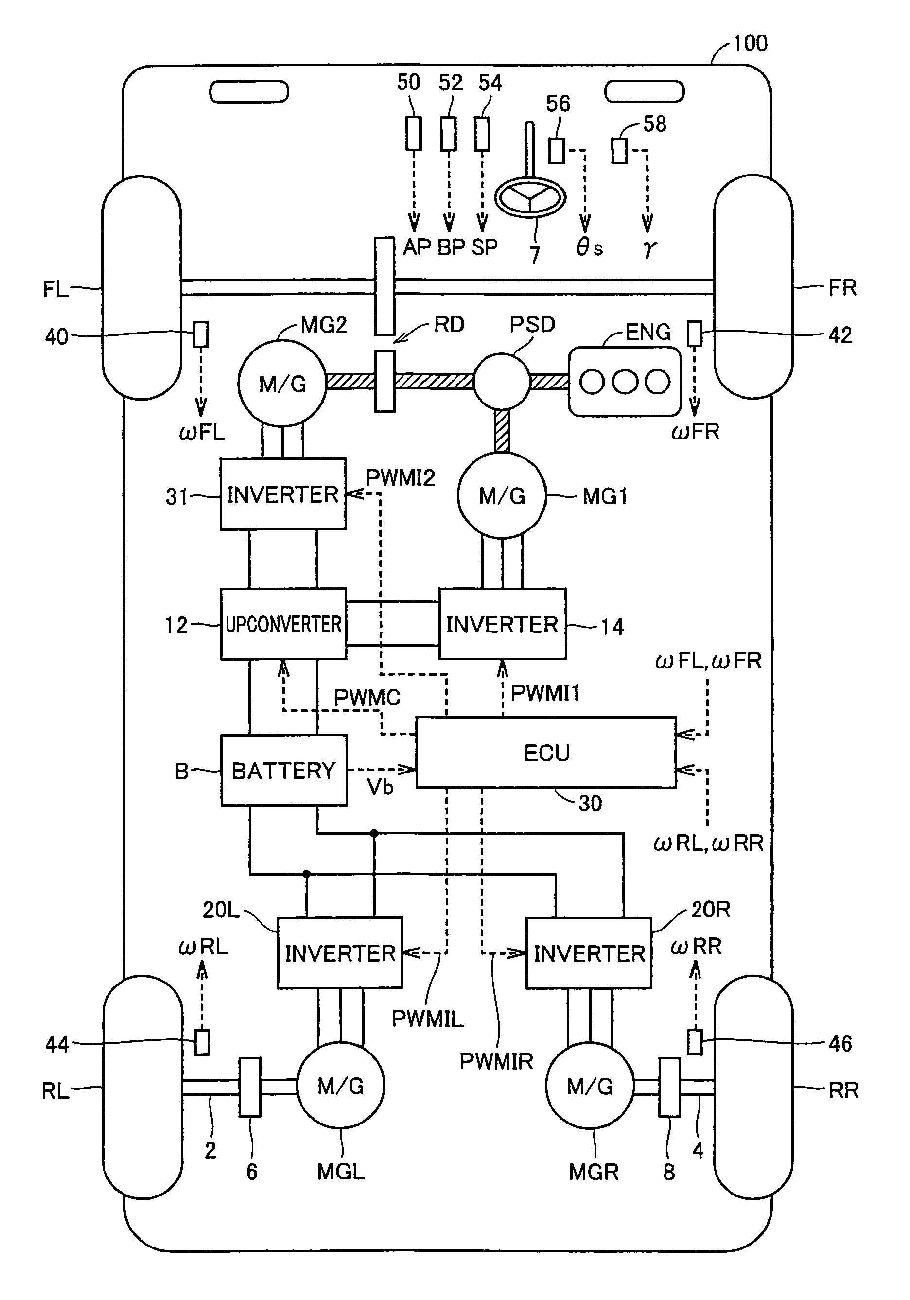
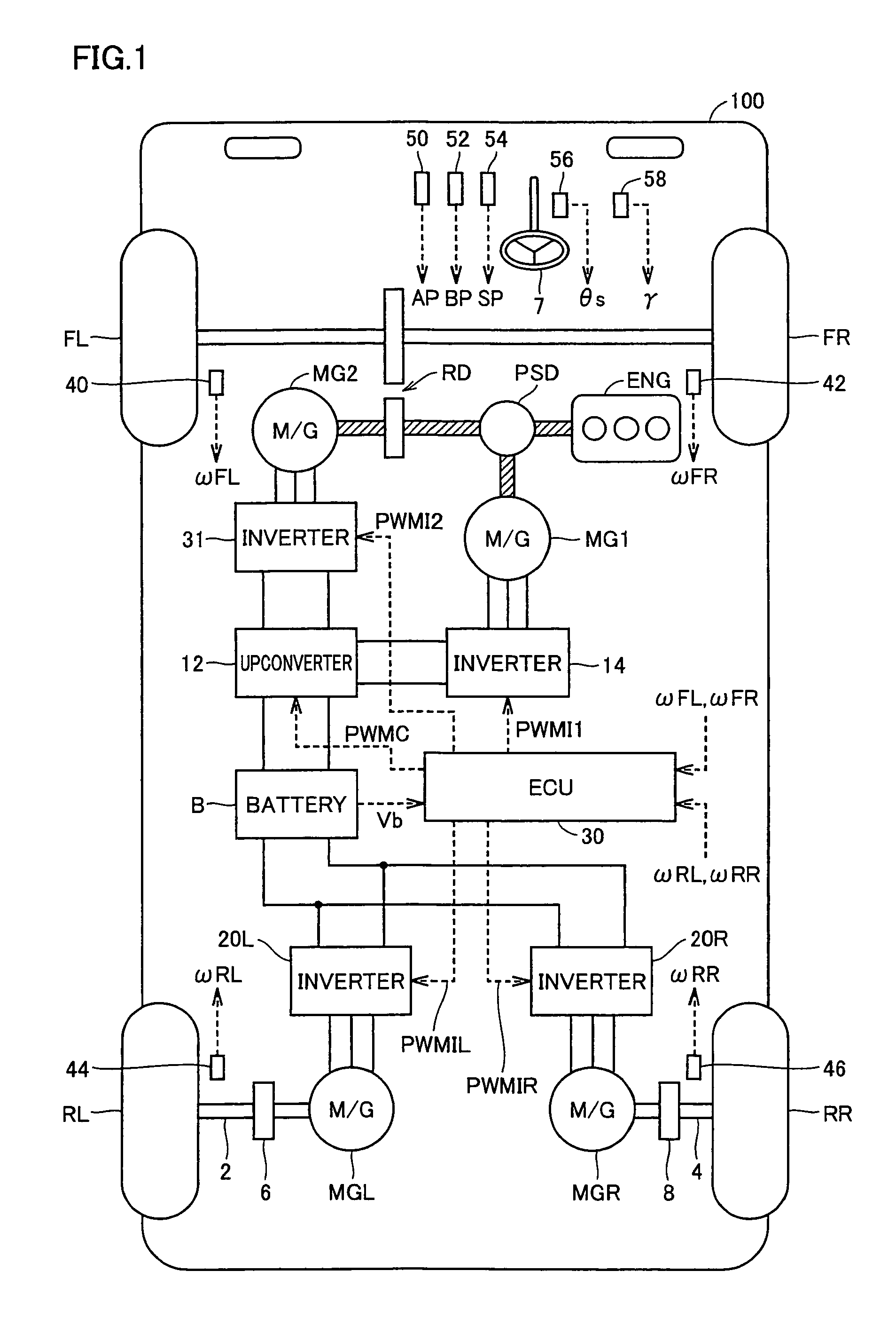
[0051]FIG. 1 is a schematic block diagram showing a drive system of a vehicle having mounted therein a driving power control apparatus for a four wheel drive vehicle in an embodiment of the present invention.

[0052]With reference to FIG. 1, a vehicle 100 is an FF based hybrid four wheel drive vehicle for example having front left and right wheel units FL, FR as main drive wheel units and rear left and right wheel units RL, RR as idler wheel units. The hybrid four wheel drive vehicle adopts a system driving two wheels independently that drives front left and right wheel units FL, FR by an engine ENG and a motor generator MG2 and drives rear left and right wheel units RL, RR by motor generators MGL, MGR independently.

[0053]Note that other than the FIG. 1 con...


PUM


Abstract

Front left and right wheel units are driven by an engine and a motor generator. Rear left and right wheel units are independently driven by in-wheel motor type motor generators. The motor generator and the motor generator are configured to have different rated outputs, respectively, and be subjected to different speed reduction ratios, respectively, between the motor generators and their respectively associated drive wheel units, and thus have characteristics, respectively, in efficiency with respect to torque and vehicular speed, that exhibit high efficiency in mutually different output ranges, respectively. When a mileage oriented mode is selected as a traveling mode, an ECU determines how a drive torque should be allocated between the motor generators, as based on the motors' required drive torque and vehicular speed and on each motor generator's characteristic in efficiency, to maximize the motor generators' total efficiency.

Description

TECHNICAL FIELD[0001]The present invention relates generally to a driving power control apparatus for a four wheel drive vehicle, and particularly to a driving power control apparatus for a four wheel drive vehicle having right and left idler wheel units driven independently by individual driving sources.BACKGROUND ART[0002]In recent years, hybrid vehicles and electric vehicles are gaining attention as environmentally friendly vehicles. A hybrid vehicle has, as a source of motive power, a conventional engine and in addition thereto a motor driven by a direct current power supply via an inverter. More specifically, the engine is driven to obtain a source of motive power and the direct current power supply also provides direct current voltage which is in turn converted by the inverter to alternate current voltage employed to rotate the motor to obtain a source of motive power.[0003]An electric vehicle is a vehicle having as a source of motive power a motor driven by a direct current p...

Claims


Application Information

Patent Timeline
Patent Type & Authority Patents(United States)
IPC IPC(8): B60L11/02B60W10/08B60W20/00B60L50/10B60L50/16
CPCB60K1/02B60L15/2045B60K6/52B60K7/0007B60K17/356B60L11/14B60W10/08B60W30/1882B60K6/445B60K17/043B60K2007/0092B60L2220/44B60L2240/423B60W20/00B60W2540/10B60W2710/083Y02T10/52Y02T10/6265Y02T10/646Y02T10/7077Y02T10/648Y02T10/6239Y02T10/70B60W10/06B60W10/119B60W20/30B60W2720/406B60L50/16Y02T10/40Y02T10/62Y02T10/64Y02T10/7072Y02T10/72Y02T10/84
Inventor MIZUTANI, RYOJITSUCHIDA, MICHITAKATAHARA, YASUAKIFUKUSHIMA, TOMOHIROSAKUMA, MASAFUMI
Owner TOYOTA JIDOSHA KK
Learn More