
Digital ballistic impact detection system

a detection system and ballistic technology, applied in the direction of instruments, force/torque/work measurement, explosion force measurement, etc., can solve the problems of traumatic brain injury diagnosis, heavy and bulky devices are not generally available near battlefields,

Inactive Publication Date: 2012-06-05
EMPIRE IP LLC
View PDF34 Cites 17 Cited by
  • Summary
  • Abstract
  • Description
  • Claims
  • Application Information

AI Technical Summary

Benefits of technology

"The present invention provides a method for estimating the magnitude of a ballistic impact by using a self-powered shock sensor that generates an electric signal proportional to the shock value of the impact. The sensor is connected to a latchable memory device that captures and stores the maximum shock value of the impact for later retrieval. The captured data may also include information about the timing of the impact or the elapsed time from the impact to the readout of the sensor information. The invention also includes an impact recorder that measures the severity of a ballistic impact experienced by a combat soldier, which can be used to assess the impact of a weapon or other impact event. The recorder includes a self-powered shock sensor and an electronic circuit to carry the electric signal away from the sensor and a latchable memory to capture and store the maximum value of the electric signal. The invention can also include an impact recorder that measures the severity of any impact event by using a self-powered shock sensor and an electronic circuit to carry the electric signal away from the sensor and a latchable memory to capture and store the maximum value of the electric signal."

Problems solved by technology

One particularly difficult injury to diagnose is Traumatic Brain Injury (TBI), which relies on an accurate determination of the magnitude of the impact or blast energy to the head of the individual.
Unfortunately, these heavy and bulky devices are not generally available near battlefields, and it could be hours or even days before the wounded combat soldier can be taken to similar assessment facilities.

Method used


Image

  • Digital ballistic impact detection system
  • Digital ballistic impact detection system
  • Digital ballistic impact detection system

Examples


exemplary embodiment 10

[0018]Illustrated in FIG. 1 is a schematic drawing of the digital ballistic impact detection system as applied in a battlefield environment. For example, the system can be mounted on a soldier's helmet and the results can be read out using a wireless reader. The detection system of the present invention can comprise, among other things, a zero-power or ultra-low power impact recorder capable of detecting, quantifying, recording and transmitting the maximum energy of a blast or impact to the head for aiding in the triage and diagnosis of Traumatic Brain Injury (TBI) in soldiers on the battlefield.

[0019]The embodiment 10 of the present invention can include a combat soldier 20 wearing a helmet 22, to which is attached an impact recorder 24 that can detect, quantify, and record the maximum value or absolute magnitude of a shock experienced by the head of the soldier, in response to the impact of a projectile or a shock wave from a nearby explosion. As can be appreciated, multiple impac...

exemplary embodiment 100

[0044]Illustrated in FIG. 5 is a perspective, cut-away view of the digital ballistic impact detection system, according to the present invention. This embodiment can include a self-powered shock sensor 110 configured to self-generate an electric signal proportional to the shock value of the ballistic impact, an electronic circuit 130 configured to carry the electric signal away from the shock sensor, and a latchable electronic memory 150 that is configured to capture the maximum value of the electric signal proportional to the value of the shock wave amplitude of the ballistic impact.

[0045]The shock sensor 110 can be fabricated using a thin-film piezoelectric deposition process and standard semiconductor fabrication techniques to form a thin film piezoelectric microcantilever. As shown in FIG. 5, a silicon wafer 102 can be covered with a plurality of surface layers 104, 106 which, for the purposes of this detailed description, can be representative of a plurality of sub-layers inclu...


PUM


Abstract

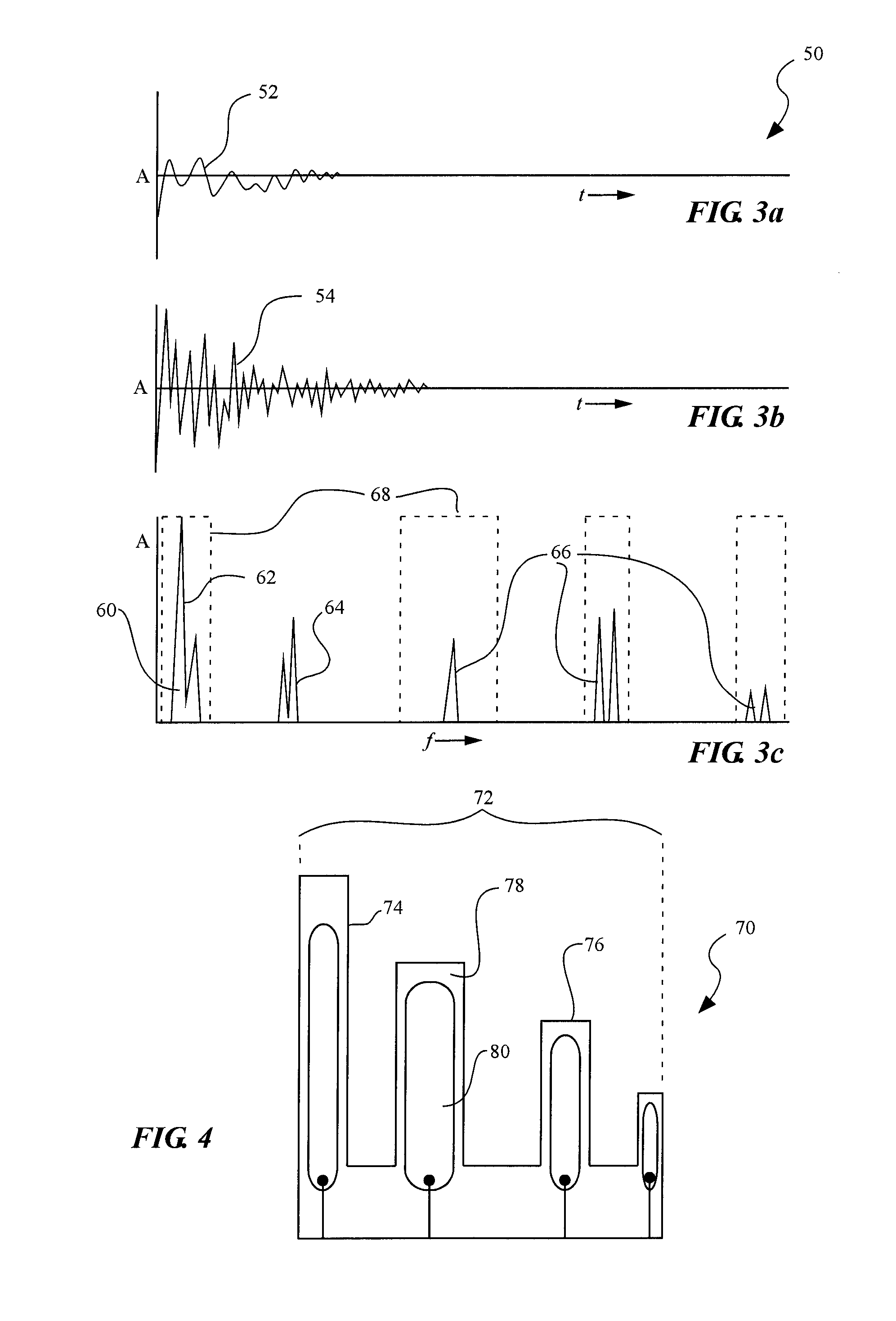
Methods and devices for a miniature, ultra-low power impact recorder for detecting, quantifying and recording the energy of an explosive blast or ballistic projectile impact. In one embodiment, the impact recorder can included a sensor comprised of an array of electromechanical resonators that is sensitive to the vibrations produced in selected, discrete frequency ranges that approximate the spectral signature characteristics of the shockwave resulting from the ballistic impact event, even after traveling through impacted material or body tissues.

Description

RELATED APPLICATIONS[0001]This application is a continuation-in-part of U.S. patent application Ser. No. 12 / 116,605, filed May 7, 2008, and entitled “Digital Wound Detection System”, which claims the benefit of U.S. Provisional Application Ser. No. 60 / 928,147, filed May 7, 2007, and entitled, “Digital Wound Detection System”, which are incorporated by reference in their entirety herein.FIELD OF THE INVENTION[0002]The present invention relates generally to methods and devices related to digital ballistic impact detection.BACKGROUND OF THE INVENTION AND RELATED ART[0003]In the modern, automated battlefield, innovations and advancements have abounded in the areas of remote surveillance, weapons systems delivery and accuracy, communications, personal protection of soldiers, etc. One area which has lagged behind is the diagnosis and treatment of wounded soldiers, which still requires trained medical personnel to accurately diagnose the severity of injuries suffered in the battlefield and...

Claims


Application Information

Patent Timeline
Patent Type & Authority Patents(United States)
IPC IPC(8): G01H1/00H10N30/88
CPCF41H1/02F41H1/04G01D21/00G01L5/0052G01L5/14
Inventor PETELENZ, TOMASZ J.JACOBSEN, STEPHEN C.
Owner EMPIRE IP LLC
Learn More