
Method for manufacturing wind turbine blade with an integrated lightning conductor

a technology of lightning conductor and wind turbine blade, which is applied in the manufacture of final products, machines/engines, forging/pressing/hammering apparatus, etc., can solve the problems of both the blade structure and the conductor cables themselves, and achieve the effect of reducing mechanical stresses on the conductor and being readily integrated

Active Publication Date: 2012-06-05
SIEMENS GAMESA RENEWABLE ENERGY AS
View PDF15 Cites 34 Cited by
  • Summary
  • Abstract
  • Description
  • Claims
  • Application Information

AI Technical Summary

Benefits of technology

The present invention provides a method for manufacturing a wind turbine blade with a lightning conductor integrated into the composite material of the blade. The lightning conductor is formed by laying a composite material around a mould and then infusing a liquid polymer into the mould to wet the composite material. The lightning conductor is covered by a high-quality vacuum-impregnated laminate that forms an integral joint with the rest of the blade, yielding maximum protection against lightning strikes. The method allows for the inclusion of the larger part of the lightning protection system during manufacturing, and the lightning conductor can be fixed in its final position by infusing resin and allowing it to set. The technical effect of the invention is to provide a wind turbine blade with improved lightning protection.

Problems solved by technology

This can cause wear to both the blade structure and the conductor cables themselves.

Method used


Image

  • Method for manufacturing wind turbine blade with an integrated lightning conductor
  • Method for manufacturing wind turbine blade with an integrated lightning conductor
  • Method for manufacturing wind turbine blade with an integrated lightning conductor

Examples


Embodiment Construction

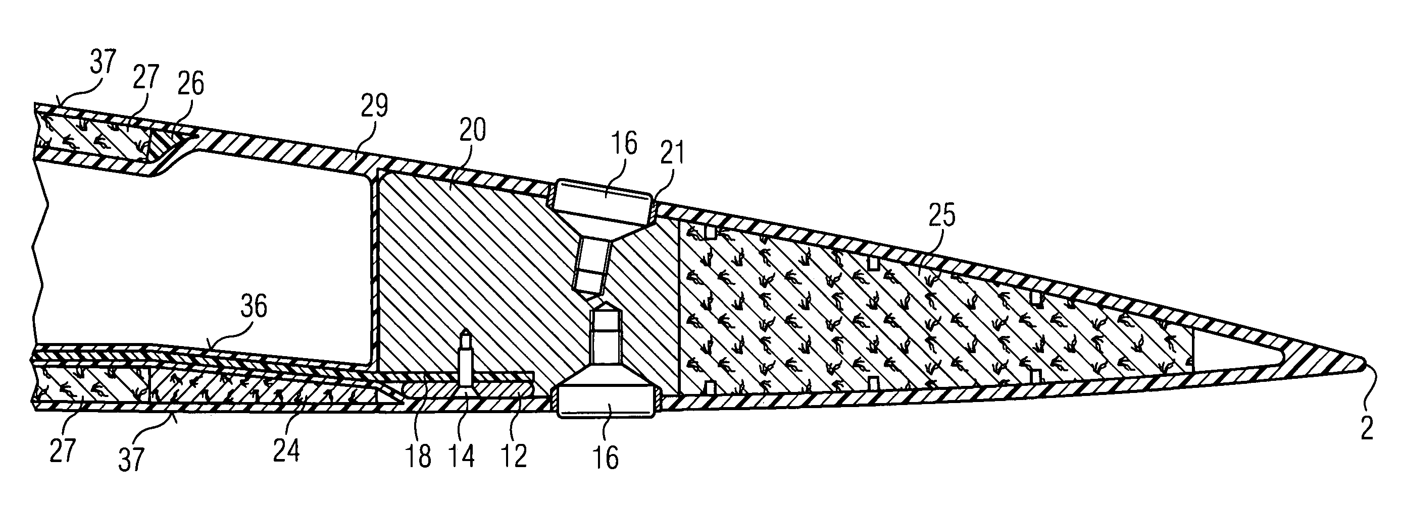
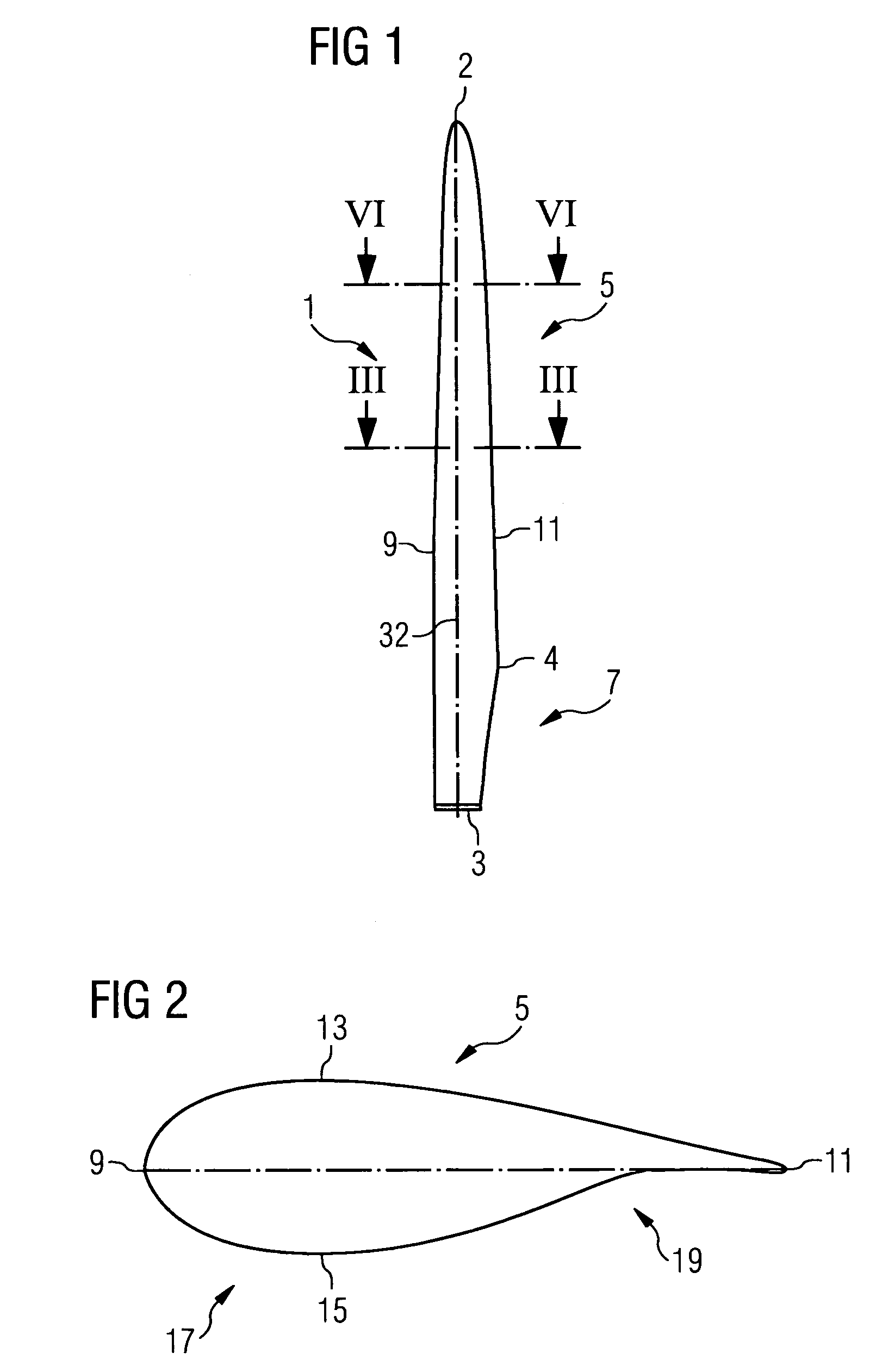
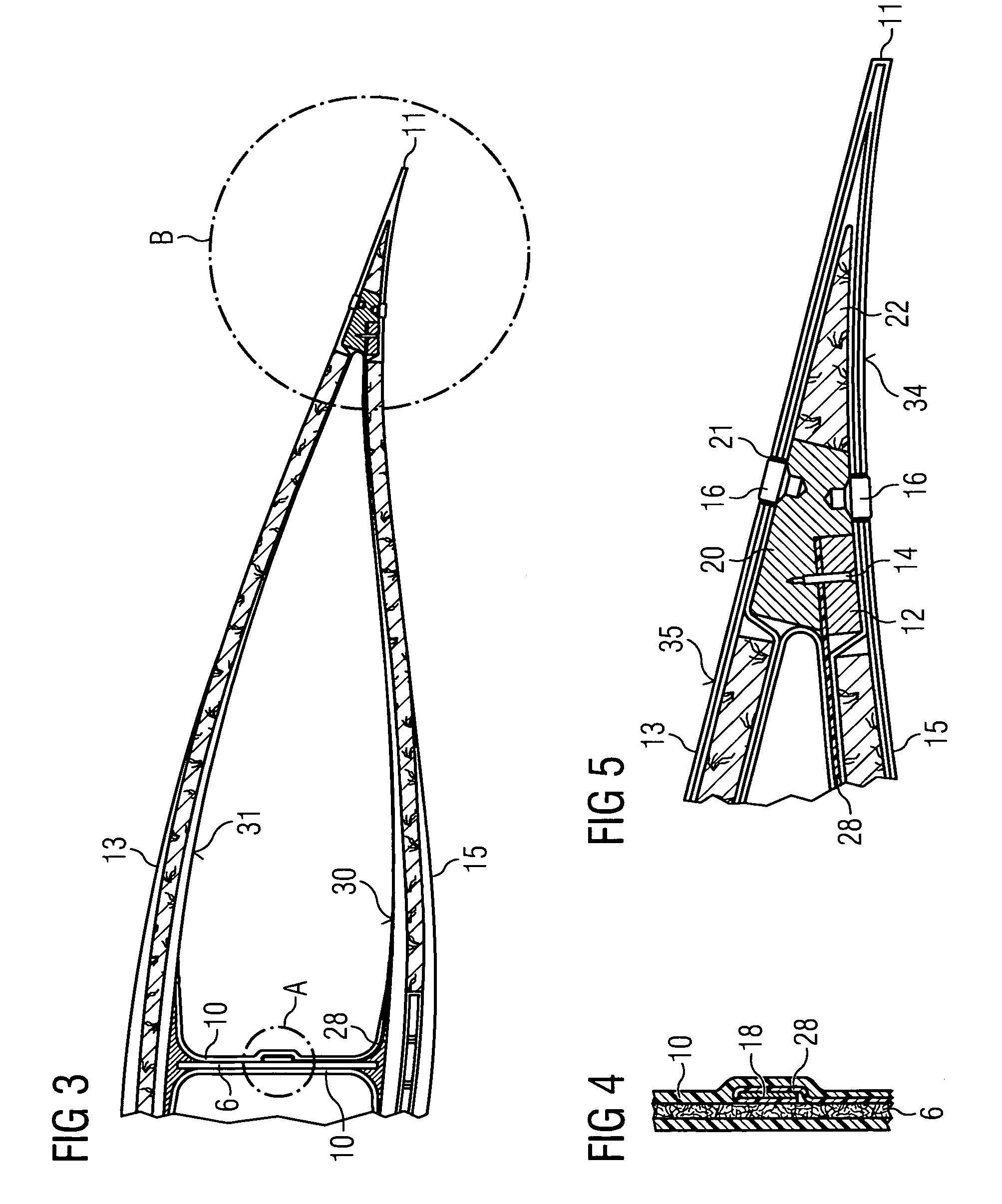
[0058]An embodiment of the present invention will now be described in detail with reference to FIGS. 1 to 14.

[0059]FIG. 1 shows a rotor blade in a plan view on the plane defined by the blade's span and the blade's chord. FIG. 1 shows a wind turbine blade 1 as it is usually used in a three-blade rotor. However, the present invention shall not be limited to blades for three-blade rotors. In fact, it may as well be implemented in rotors with more or less than three blades, e.g. two-blade rotors. The centreline of the blade 1 is indicated by reference numeral 32.

[0060]The rotor blade 1 shown in FIG. 1 comprises a root portion 3 with a cylindrical profile and a tip 2. The tip forms the outermost part of the blade. The cylindrical profile of the root portion 3 serves to fix the blade to a bearing of a rotor hub. The rotor blade 1 further comprises a so-called shoulder 4 which is defined as the location of its maximum profile depth, i.e. the maximum chord length of the blade. Between the s...


PUM

PropertyMeasurementUnit
distanceaaaaaaaaaa
distanceaaaaaaaaaa
shapeaaaaaaaaaa

Abstract

A method is provided for manufacturing a wind turbine rotor blade in which the blade is formed as a laminated structure by laying a composite material of fiber reinforcement material and / or core material in a mold defining the shape of the blade; evacuating the mold after laying the composite material; introducing a liquid polymer into the evacuated mold and wetting the composite material; curing the liquid polymer after the composite material has been wetted; and removing the mold after curing the liquid. At least one lightning conductor is integrated into the composite material before wetting it with the liquid polymer. Moreover, a wind turbine rotor blade made from a single laminated structure is provided with at least one lightning conductor is integrated into the laminated structure.

Description

CROSS REFERENCE TO RELATED APPLICATIONS[0001]This application claims priority of European Patent Office application No. 08007393.5 EP filed Jul. 15, 2004, which is incorporated by reference herein in its entirety.FIELD OF INVENTION[0002]The present invention relates to a method for manufacturing a wind turbine rotor blade with an integrated lightning conductor. The invention further relates to a wind turbine blade with an integrated lightning conductor.BACKGROUND OF INVENTION[0003]Lightning conductor cables in wind turbine blades that are only attached to the blade structure at certain points are to a certain extent able to move when the turbine is in operation. This can cause wear to both the blade structure and the conductor cables themselves.SUMMARY OF INVENTION[0004]Traditionally, the lightning conductor of a wind turbine blade has taken the form of a metal wire affixed to the interior structure of the blade. For example, in WO 2007 / 062659 A1 a lightning protection system for a ...

Claims


Application Information

Patent Timeline
Patent Type & Authority Patents(United States)
IPC IPC(8): B21D53/78B29D99/00
CPCF03D11/0033F03D1/0683B29L2031/085F05B2240/30Y02E10/721Y10T29/49321Y10T29/49316Y10T29/49337Y02E10/722F03D80/30Y02E10/72Y02P70/50F03D1/0675
Inventor KRISTENSEN, JENS JORGEN OSTERGAARDOLSEN, KAJ
Owner SIEMENS GAMESA RENEWABLE ENERGY AS
Learn More