
Method for forming an object

a technology of object and object, which is applied in the direction of casting apparatus, crystal growth process, heat treatment process control, etc., can solve the problems of parts warping, troublesome and time-consuming or impossible to remove, and parts that are difficult to us

Inactive Publication Date: 2012-05-29
UNIV OF SHEFFIELD
View PDF20 Cites 38 Cited by
  • Summary
  • Abstract
  • Description
  • Claims
  • Application Information

AI Technical Summary

Problems solved by technology

The above processes when applied to metal powders often induce a rapid melting and re-solidification of material that causes large internal thermal stresses that may cause a part to warp during and after solidification.
These anchors are usually made from the same metal used to produce the part and are often troublesome and time consuming or impossible to remove after producing the part.
Removal of anchors can also damage components causing the part to be unusable.

Method used


Image

  • Method for forming an object
  • Method for forming an object
  • Method for forming an object

Examples


Embodiment Construction

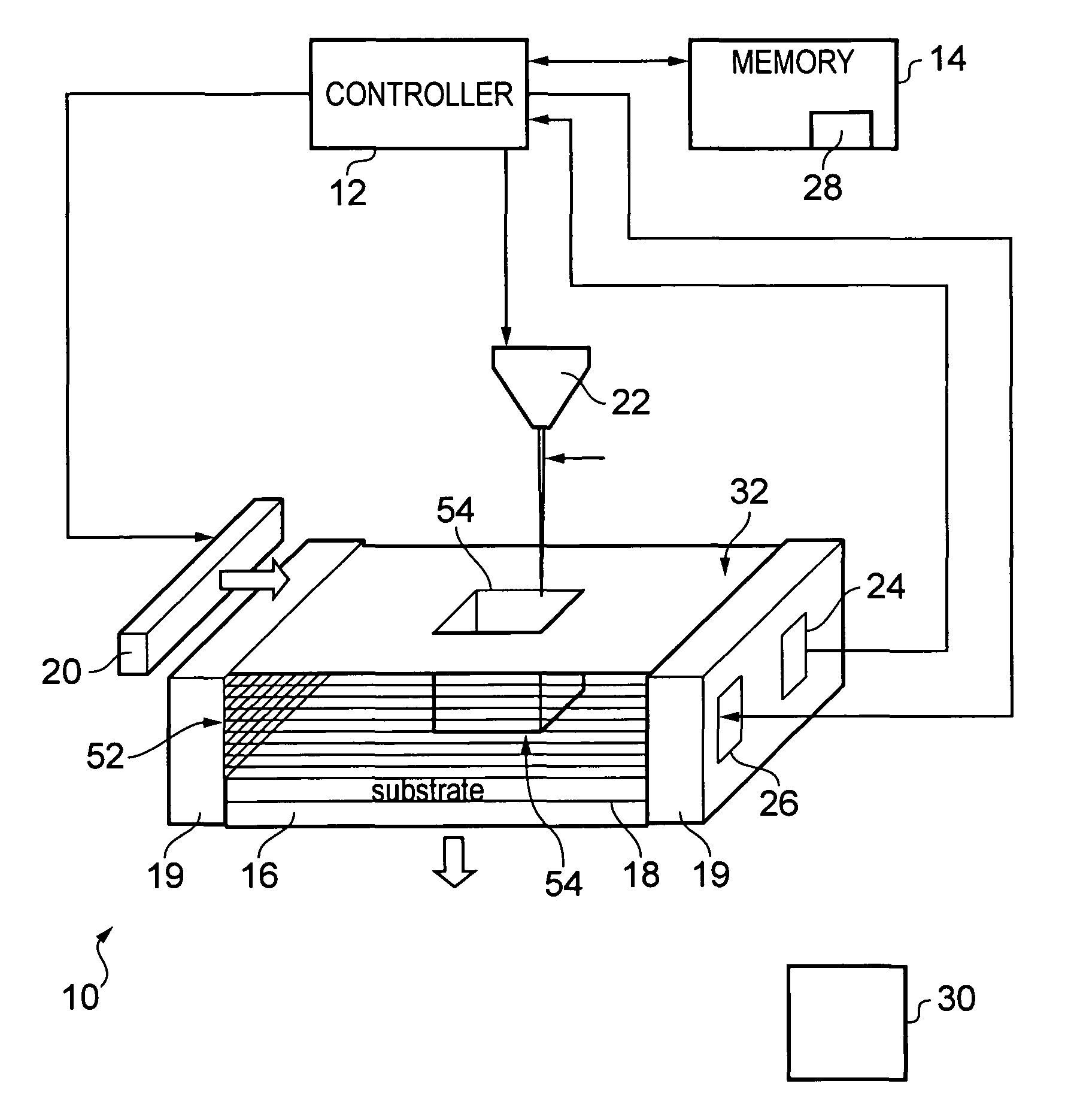
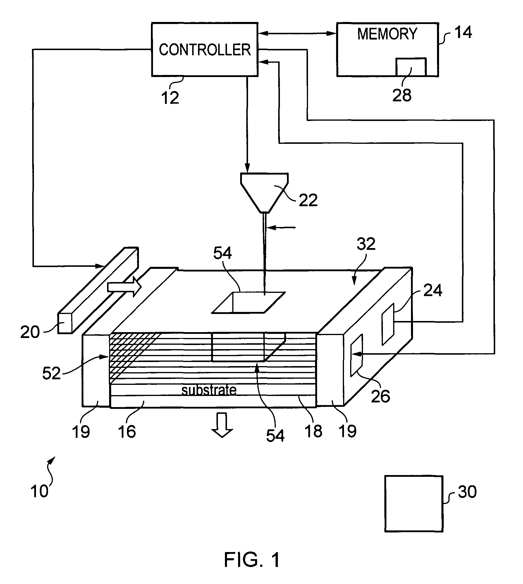
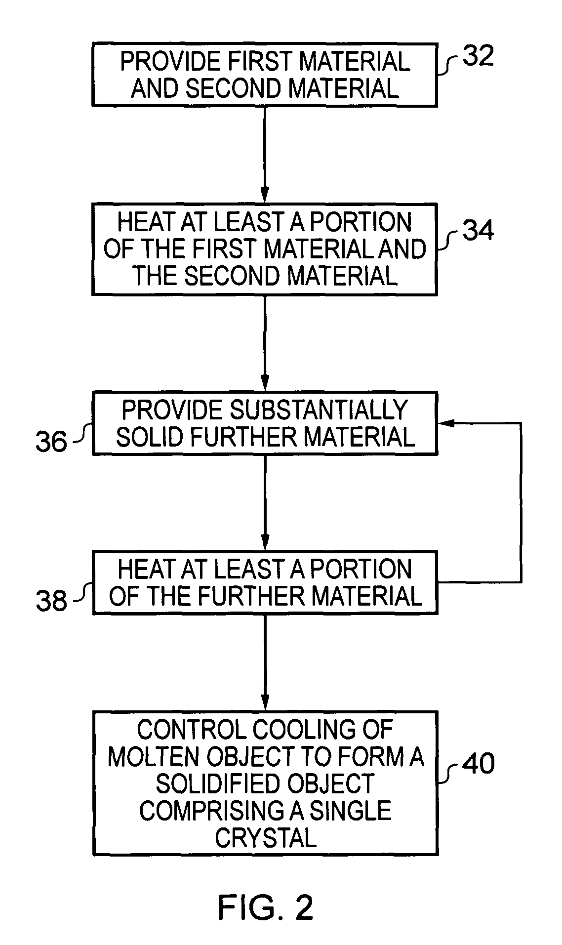
[0006]According to various, but not necessarily all, embodiments of the invention there is provided a method for forming an object, comprising: providing at least a first material having a melting point at a first temperature and a second material having a melting point at a second temperature; heating at least a portion of the first and second materials above the first and second temperatures to form a substantially molten alloy, the molten alloy having a solidifying point at a third temperature, the third temperature being less than the first temperature and the second temperature; and providing substantially solid further material to at least a portion of the molten alloy, the further material having a melting point at a temperature greater than the third temperature.

[0007]When the substantially solid further material is provided to at least a portion of the molten alloy, the substantially molten alloy may have a temperature above which the alloyed material does not substantially...


PUM

PropertyMeasurementUnit
temperaturesaaaaaaaaaa
temperatureaaaaaaaaaa

Abstract

A method for forming an object, including providing at least a first material having a melting point at a first temperature and a second material having a melting point at a second temperature; heating at least a portion of the first and second materials above the first and second temperatures to form a substantially molten alloy, the molten alloy having a solidifying point at a third temperature, the third temperature being less than the first temperature and the second temperature; and providing substantially solid further material to at least a portion of the molten alloy, the further material having a melting point at a temperature greater than the third temperature.

Description

FIELD OF THE INVENTION[0001]Embodiments of the present invention relate to a method, apparatus, computer readable storage medium and computer program for forming an object.BACKGROUND TO THE INVENTION[0002]Solid Freeform Fabrication (SFF) is a group of manufacturing technologies that are capable of producing 3D solid parts by a consecutive layer-wise shaping and consolidation of material (e.g. in the form of powder). Part geometric data can be taken directly from a Computer Aided Design (CAD) model and processed to form an object without the need for any moulds or tools. Various materials and combinations of materials such as plastics, waxes, metals and ceramics can be processed according to the process used.[0003]The production of fully functional parts with high densities in a single step often requires the complete melting of powder particles. This can be achieved with the use of high energy densities (e.g. a laser beam or an electron beam) that can generate temperatures capable o...

Claims


Application Information

Patent Timeline
Patent Type & Authority Patents(United States)
IPC IPC(8): B22D46/00
CPCB22D23/06B22D27/04B22D46/00B22F3/1055C30B11/00C30B29/52B22F2003/1057Y02P10/25B22F10/28B22F10/368B22F12/13B22F12/17B22F12/20B22F12/90B33Y40/00B33Y10/00
Inventor FURLONG, MICHAEL THOMASHOPKINSON, NEILMUMTAZ, KAMRAN AAMIR
Owner UNIV OF SHEFFIELD
Learn More