
Radio coexistence mechanism for variable data rate radio links

a radio link and variable data technology, applied in the field of radio transmitters, can solve problems such as troublesome conflicts, and achieve the effect of avoiding or reducing the risk of a data rate controller

Active Publication Date: 2012-05-22
STMICROELECTRONICS INT NV +1
View PDF13 Cites 9 Cited by
  • Summary
  • Abstract
  • Description
  • Claims
  • Application Information

AI Technical Summary

Benefits of technology

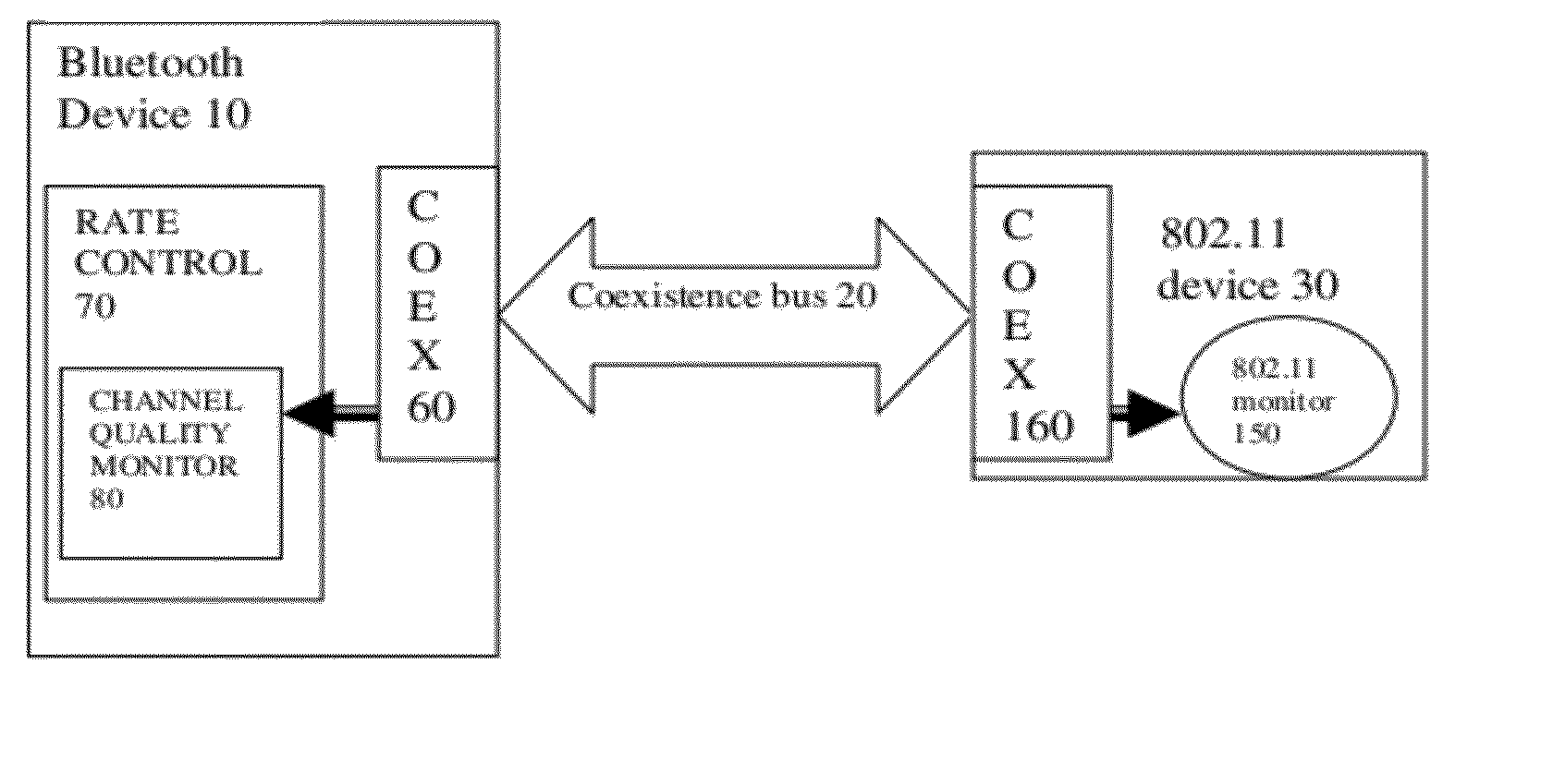
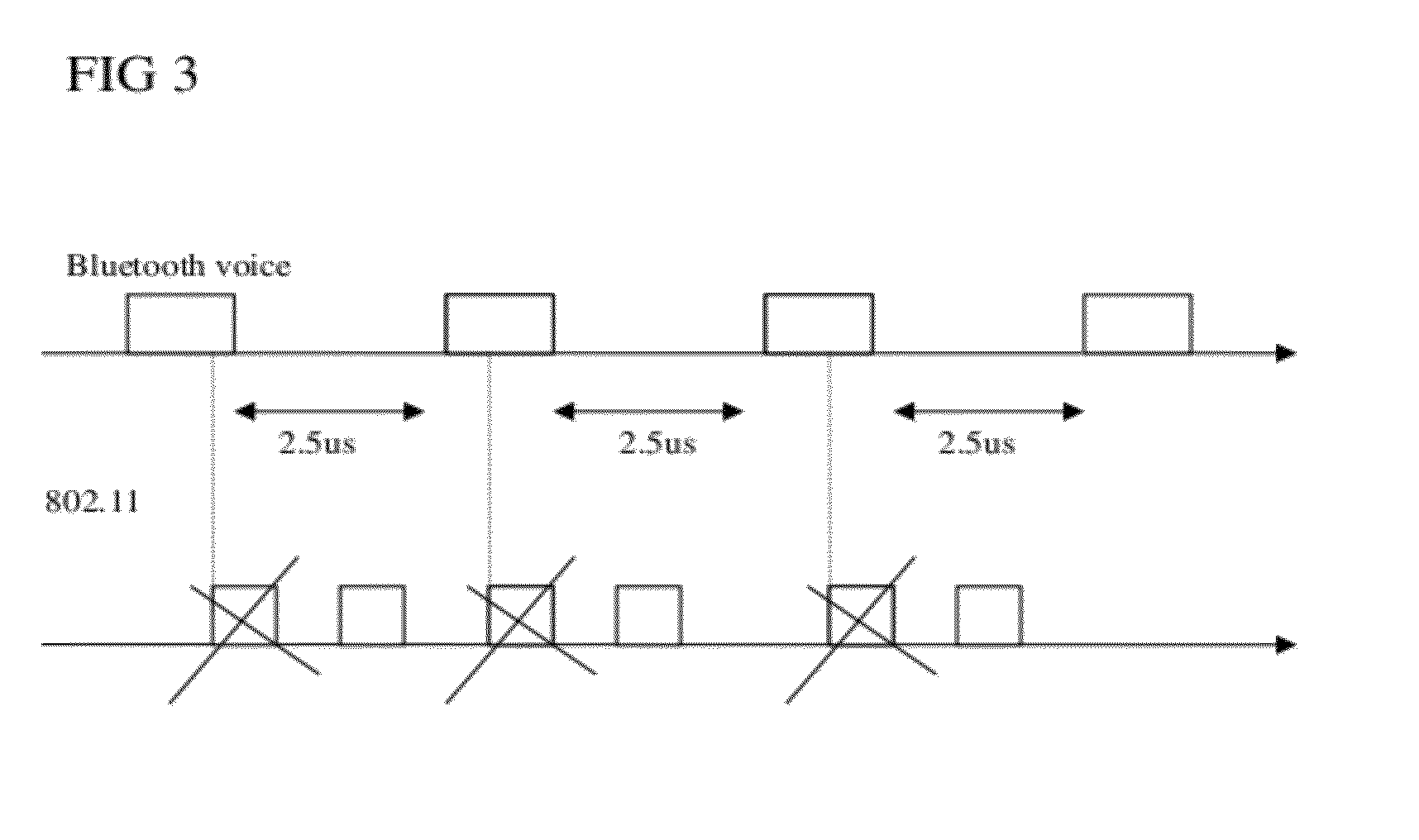
[0010]By making the link monitor dependent on an input from the coexistence controller, a number of consequences can arise. For example the link monitor can more easily distinguish between transmission losses caused by the coexistence control, and those caused by other effects. This in turn can help avoid or reduce the risk of a data rate controller being fooled into unnecessarily reducing a transmission rate if transmission losses caused by the coexistence control are misinterpreted as a drop in link quality. The monitor output can be used for purposes other than rate control. Other consequences can be envisaged. Embodiments of the invention can involve any type of radio transmitter, any form of coexistence interface, and any form of link monitor. Embodiments can have any other additional features. Some additional features are described in more detail below. For example, the monitoring of an error rate of the link can be suspended in accordance with an output from the coexistence controller. Or the error rate can be determined by ignoring errors that occur during the a time determined by the output of the coexistence controller, i.e. during the time that the coexistence controller prevents one of the devices from transmitting.

Problems solved by technology

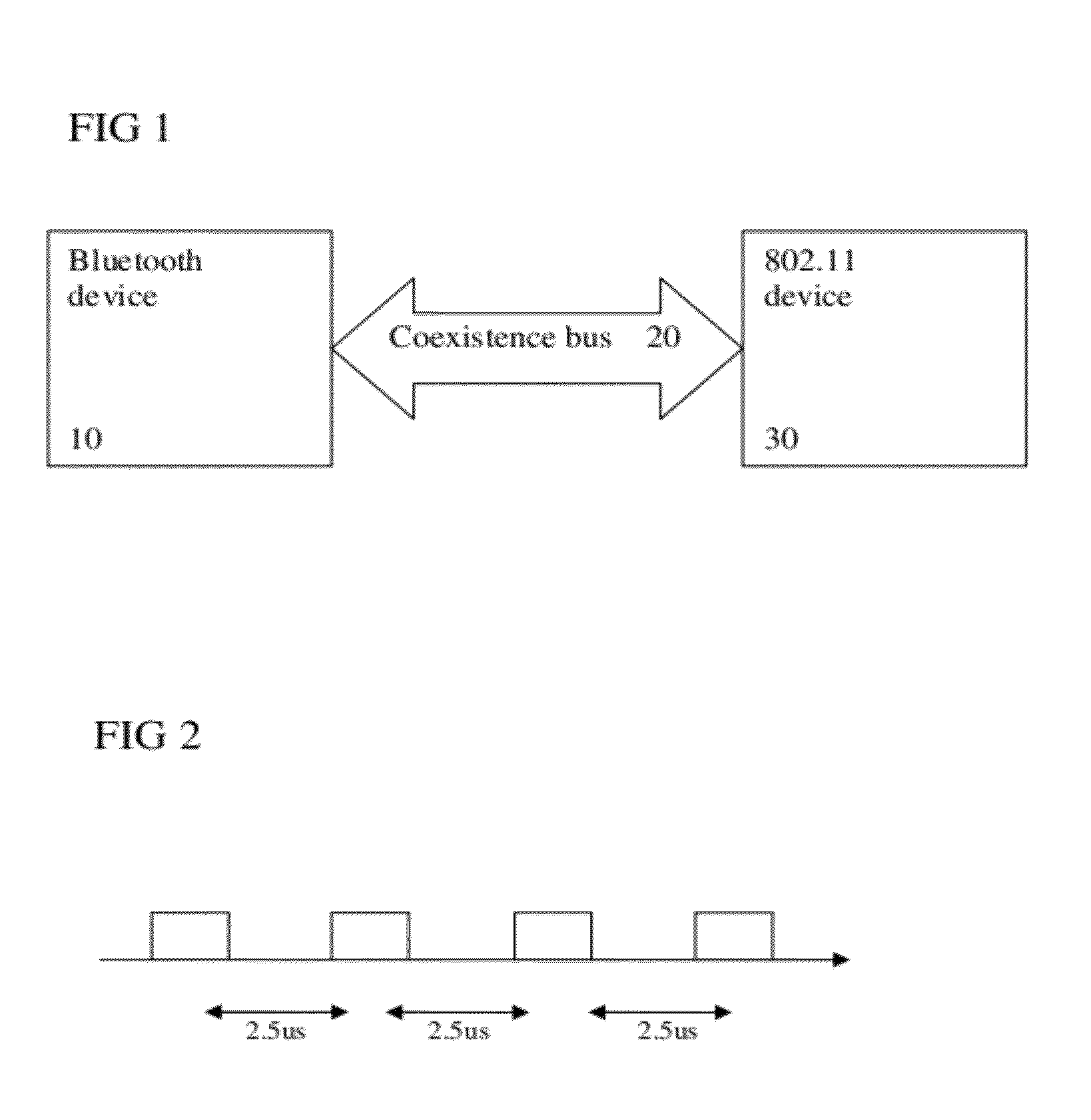
Conflicts can be very troublesome when the transmitters are very close to each other, e.g. a lap top computer with both a wireless Bluetooth and a “WiFi” (IEEE 802.11) transmitter operating in the same frequency band.

Method used


Image

  • Radio coexistence mechanism for variable data rate radio links
  • Radio coexistence mechanism for variable data rate radio links
  • Radio coexistence mechanism for variable data rate radio links

Examples


Embodiment Construction

[0020]The present invention will be described with respect to particular embodiments and with reference to certain drawings but the invention is not limited thereto but only by the claims. The drawings described are only schematic and are non-limiting. In the drawings, the size of some of the elements may be exaggerated and not drawn on scale for illustrative purposes. Where the term “comprising” is used in the present description and claims, it does not exclude other elements or steps. Where an indefinite or definite article is used when referring to a singular noun e.g. “a” or “an”, “the”, this includes a plural of that noun unless something else is specifically stated.

[0021]The term “comprising”, used in the claims, should not be interpreted as being restricted to the means listed thereafter; it does not exclude other elements or steps. Thus, the scope of the expression “a device comprising means A and B” should not be limited to devices consisting only of components A and B. It ...


PUM


Abstract

A device has a radio transmitter for a first radio link such as a Bluetooth link, having a coexistence controller arranged to communicate with a co-located other radio transmitter for another radio link, to enable both radio links to use potentially conflicting transmission frequencies. A link monitor monitors the first radio link, according to an output from the coexistence controller. By making the link monitor dependent on the coexistence controller, it can distinguish between transmission losses caused by the coexistence interface, and those caused by other effects, to reduce the risk of a data rate controller unnecessarily reducing a transmission rate if transmission losses caused by the coexistence control are misinterpreted as a drop in link quality.

Description

BACKGROUND OF THE INVENTION[0001]1. Field of the Invention[0002]This invention relates to devices having a radio transmitter with a coexistence controller, to corresponding methods of controlling transmissions, and to integrated circuits or software for carrying out such methods.[0003]2. Discussion of the Related Art[0004]It is known to provide radio links with automatically variable data rates. If the channel quality of the link changes owing to fading caused by movement or other changes in the air transmission path, this can be detected by a monitor and the data rate can be changed to suit or maximize the data transmissible over the link at the given time. It is also known to provide a coexistence control arranged to communicate with another radio transmitter suitable for part of another radio link, to control transmissions to enable both radio links to use potentially conflicting transmission frequencies.[0005]Conflicts between wireless transmissions using the same frequency band...

Claims


Application Information

Patent Timeline
Patent Type & Authority Patents(United States)
IPC IPC(8): H04B17/00H04W24/00H04W28/04H04W28/22H04W72/02H04W84/18H04W88/06
CPCH04L1/0003H04L1/0018H04L1/1867H04W72/02H04W24/00H04W28/04H04W28/22H04W84/18H04W88/06
Inventor CAPRETTA, PIETROCHARLIER, VINCENT
Owner STMICROELECTRONICS INT NV
Learn More