
Mirror monochromator for charged particle beam apparatus

a particle beam and mirror monochromator technology, applied in the direction of beam deviation/focusing by electric/magnetic means, magnetic discharge control, instruments, etc., can solve the problems of reducing the reliability of operation under heavy electron bombardment, and affecting the efficiency of beam deviation/focusing

Active Publication Date: 2012-05-22
ELECTRON OPTICA
View PDF27 Cites 21 Cited by
  • Summary
  • Abstract
  • Description
  • Claims
  • Application Information

AI Technical Summary

Benefits of technology

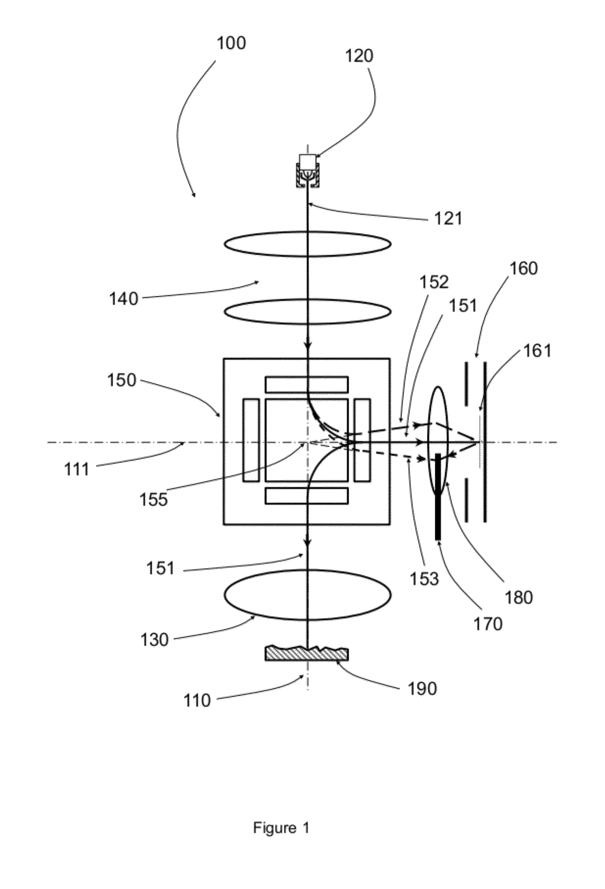
[0011]One embodiment pertains to an apparatus for generating a nearly monochromatic illumination electron beam. An electron beam source is configured to generate an electron beam, and condenser lenses focus the beam into a magnetic beam separator. After a 90 degree deflection, the beam separator introduces an angular dispersion that disperses the incoming electron beam according to its energy. A knife-edge plate removes either the high or low energy tail

Problems solved by technology

However, the energy dispersion of the Wien filter is rather low, and extremely narrow energy-selecting slits, 0.1 micrometer wide or smaller, must be employed.
The manufacture of such fine structures is rather complicated and the reliability of operation under heavy electron bombardment is reduced due to hydrocarbon contamination.
In addition, the design of the Wien filter and its electronic components is complicated due to the fact that the components are floating at high electrical potential.
However, the energy dispersion of the omega-type energy filter is still low.
The manufacture of such fine structures with straight and parallel edges is rather complicated.
In addition, the design of the omega filter and its electronic components is complicated due to the fact that the components are floating at high electrical potential.

Method used


Image

  • Mirror monochromator for charged particle beam apparatus
  • Mirror monochromator for charged particle beam apparatus
  • Mirror monochromator for charged particle beam apparatus

Examples


Embodiment Construction

Electron Mirror-Based Monochromator

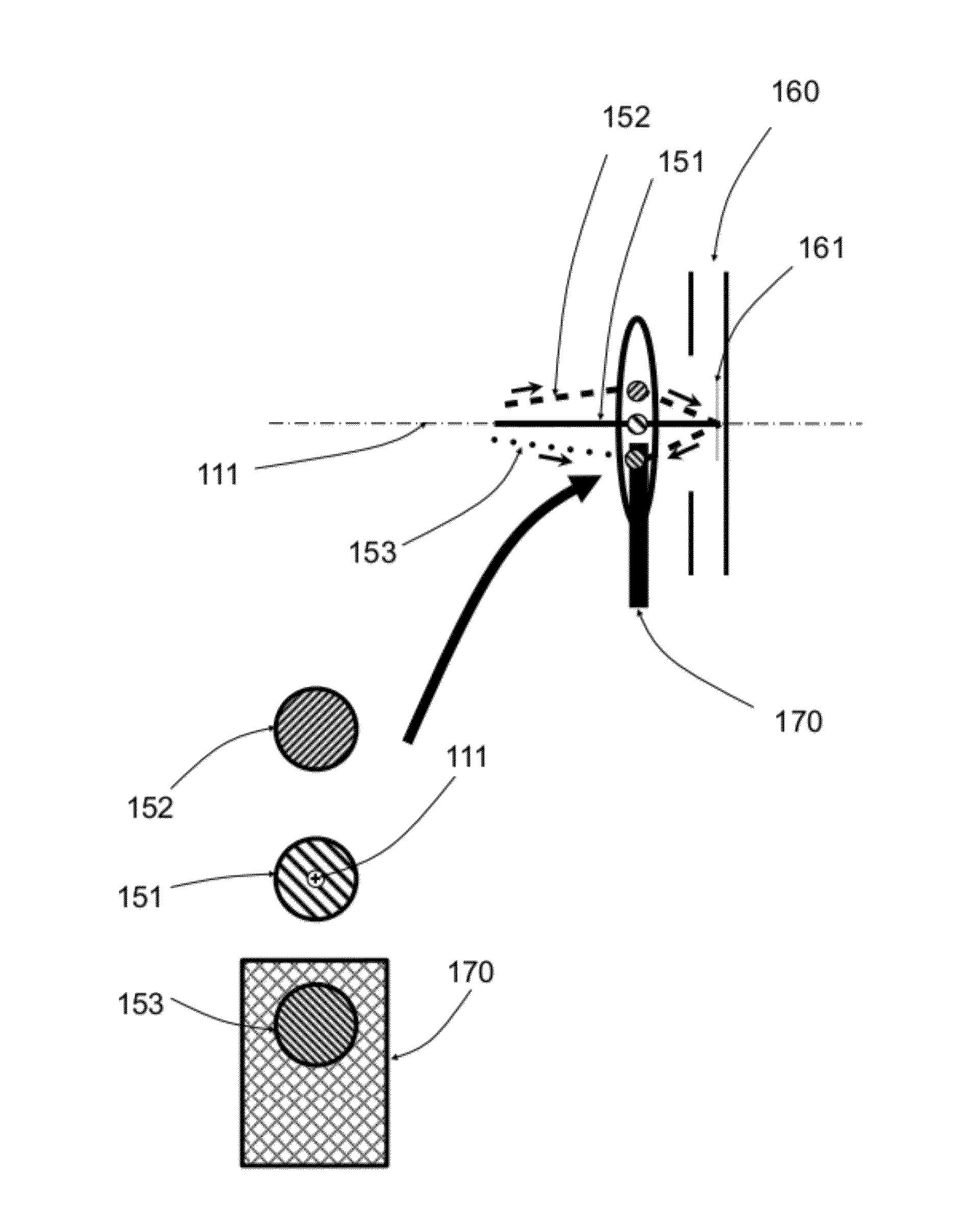
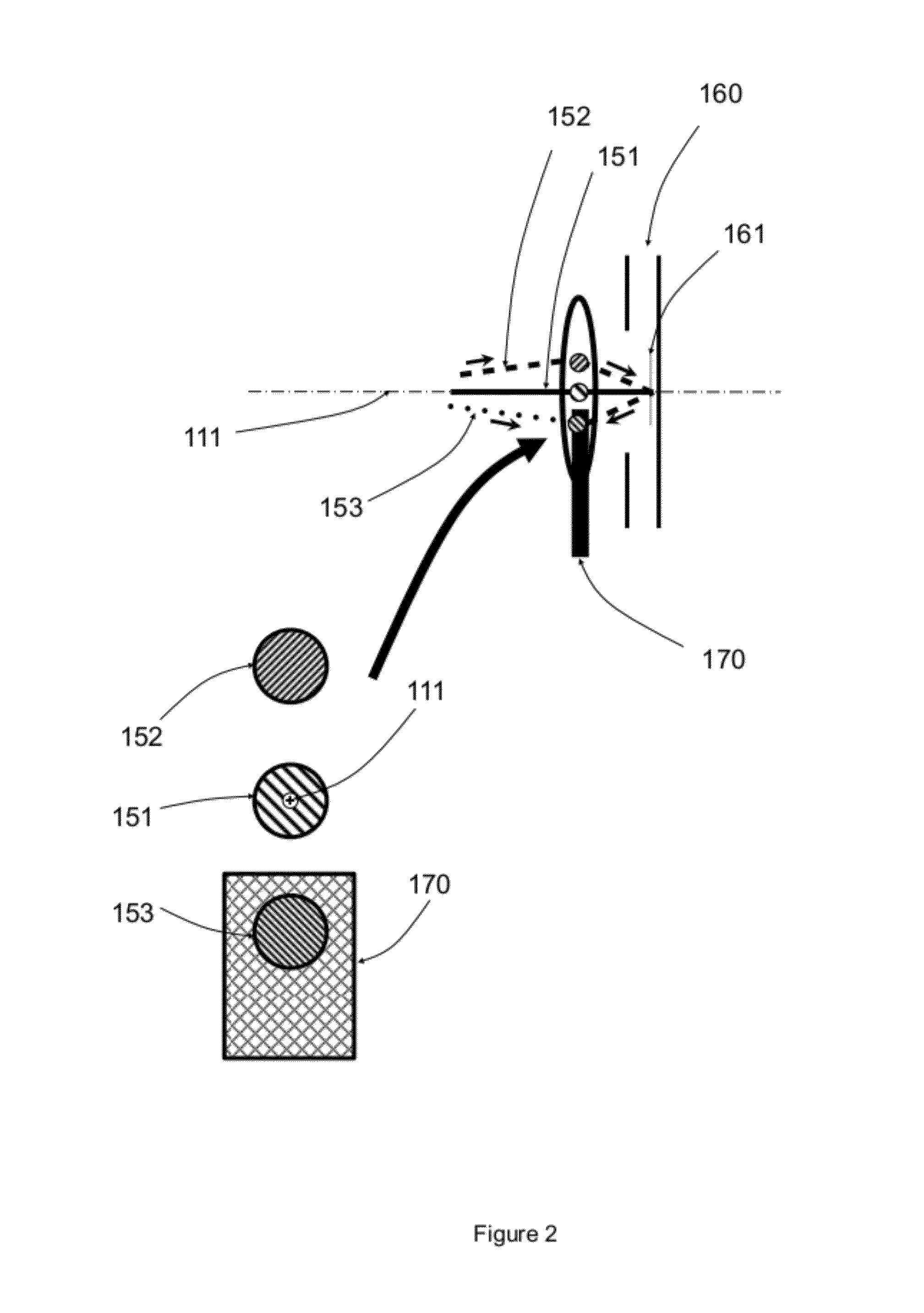
[0019]FIG. 1 is a diagram depicting a structure for an electron beam apparatus 100 comprising a prism separator and an electron mirror that are configured as an electron beam monochromator. In this apparatus 100, an electron gun 120 generates a primary electron energy beam 121 with an energy spread ΔE along the microscope axis 110 defined by the objective lens 130. One or more condenser lenses 140 collimate the primary beam into the prism separator 150, an energy dispersive element composed of an array of uniform magnetic fields of different length and strength so as to provide a mechanism for simultaneous deflection and stigmatic focusing. An optimized prism separator 150 simultaneously images stigmatically the primary beam 121 and deflects this beam by 90 degrees into the horizontal axis 111 defined by electron mirror 160. The electrons 151 with nominal beam energy E0 are deflected by 90 degrees, while electrons 152 with slightly lower energy are...


PUM


Abstract

One embodiment relates to an apparatus for generating a charged particle beam with reduced energy width. A charged particle source is configured to generate a charged particle beam with a range of energies. An energy-dispersive device bends the high-energy component of the charged particle beam at less of an angle in comparison to the bending angle of the low-energy component of the charged particle beam, such that the higher and lower energy charged particle beam components exit the energy-dispersive device at different angles of trajectory. A charged particle mirror reflects the charged particle beam such that charged particles entering at an angle with respect to the normal to the mirror reflection plane exit the mirror symmetrically with respect to the normal and at the same angle. Charged particle lenses converge all energy components exiting the energy-dispersive device at different angles of trajectory at the charged particle mirror reflection plane. A knife-edge plate removes all charged particles with energies higher and lower than a selected energy width. Other embodiments are also disclosed.

Description

BACKGROUND OF THE INVENTION[0001]1. Field of the Invention[0002]The present invention relates generally to charged particle beam apparatus, and more specifically to electron microscopy and electron beam patterning methods.[0003]2. Description of the Background Art[0004]Optical microscopes, the simplest and most used instruments used to image objects too small for the naked eye to see, uses photons with visible wavelengths for imaging. The specimen is illuminated with a broad light beam, and a magnified image of the specimen can be observed using an eye piece or camera. The maximum magnification of a light microscope can be more than 1000× with a diffraction-limited resolution limit of a few hundred nanometers. Improved spatial resolution in an optical microscope can be achieved when shorter wavelengths of light, such as the ultraviolet, are utilized for imaging.[0005]An electron microscope is a type of microscope that uses electrons to illuminate the specimen and create a magnified ...

Claims


Application Information

Patent Timeline
IPC IPC(8): H01J49/42H01J47/00H01J40/00H01J1/50
CPCH01J37/05H01J37/26H01J2237/28H01J2237/2802H01J2237/31789H01J2237/0535
Inventor MANKOS, MARIAN
Owner ELECTRON OPTICA
Learn More