
Providing improved high resolution image

a high-resolution image and high-resolution technology, applied in image data processing, instruments, television systems, etc., can solve the problems of motion blur in images, degraded capture image quality, increased noise within images, etc., to improve high resolution, improve high resolution images, and improve high resolution images

Inactive Publication Date: 2012-05-15
MONUMENT PEAK VENTURES LLC
View PDF30 Cites 34 Cited by
  • Summary
  • Abstract
  • Description
  • Claims
  • Application Information

AI Technical Summary

Benefits of technology

[0024]An advantage of the present invention is that an improved high resolution image is produced with basic changes to the image processing software without having to use a photographic flash or long exposure times to properly expose a single image.
[0025]A further advantage of the present invention is that an improved high resolution image isproduced without the need for costly special lenses with laterally moveable lens elements.
[0026]A further advantage of the present invention is that an improved high resolution image is produced without increased buffer memory requirements for storing multiple high resolution images.
[0027]A further advantage of the present invention is that an improved high resolution image is produced without the need for computationally complex de-blurring algorithms.
[0028]A still further advantage of the present invention is that it can produce a high resolution image having reduced motion blur and reduced noise.

Problems solved by technology

A problem to be addressed is light deficient photography in the presence of motion during image capture causing motion blur in the image.
However, as the exposure time required to get an image with a high signal-to-noise ratio becomes longer relative to the motion that is present during the image capture, or the available light decreases, captured image quality degrades in the form of increased motion blur and increased noise within the image.
For consumer digital cameras, there is a trend for the size of the pixels to get smaller over time, which decreases the available area to capture light during the exposure, so that noise becomes more of a problem.
Exposure times are increased to compensate for smaller pixels, but then motion blur becomes more of a problem.
Several compromises are made in photographic space to increase spatial resolution, temporal resolution or image quality, but, it is important to note that with each gain there will also be losses.
For instance, the exposure time is decreased to reduce motion blur thereby increasing temporal resolution, but at the expense of increasing noise in the image.
Additionally, there are image capture situations for which a flash is either not available or not beneficial.
However, optically based image stabilization can only be used to reduce motion blur from camera motion (global motion).
Additionally, optical image stabilization increases the cost and weight associated with the image capture device.
However, binning is accompanied by a decrease in spatial resolution.
The drawbacks of these approaches include a requirement for additional buffer memory to store multiple high resolution images, additional complexity to process multiple high resolution images and potential gaps in time between the two image captures.
Drawbacks of this and similar approaches include high computational complexity and sensitivity to noise.
While multiple low resolution video images are read out relatively quickly (30-60 images / sec is typical), and the images typically have lower noise since the pixels are often binned, the single image that is formed is limited to relatively low resolution.
However, high resolution images typically are noisier since the pixels are smaller and more significantly, a relatively large amount of time is required to readout multiple high resolution images (1.5-7 images / sec is typical) due to hardware limitations.
In addition, the problem of aligning the images grows large due to significant motion between the image captures.

Method used


Image

  • Providing improved high resolution image
  • Providing improved high resolution image
  • Providing improved high resolution image

Examples


Embodiment Construction

[0038]Because digital cameras employing imaging devices and related circuitry for signal capture and correction and for exposure control are well known, the present description will be directed in particular to elements forming part of, or cooperating more directly with, method and apparatus in accordance with the present invention. Elements not specifically shown or described herein are selected from those known in the art. Certain aspects of the embodiments to be described are provided in software. Given the system as shown and described according to the invention in the following materials, software not specifically shown, described or suggested herein that is useful for implementation of the invention is conventional and within the ordinary skill in such arts.

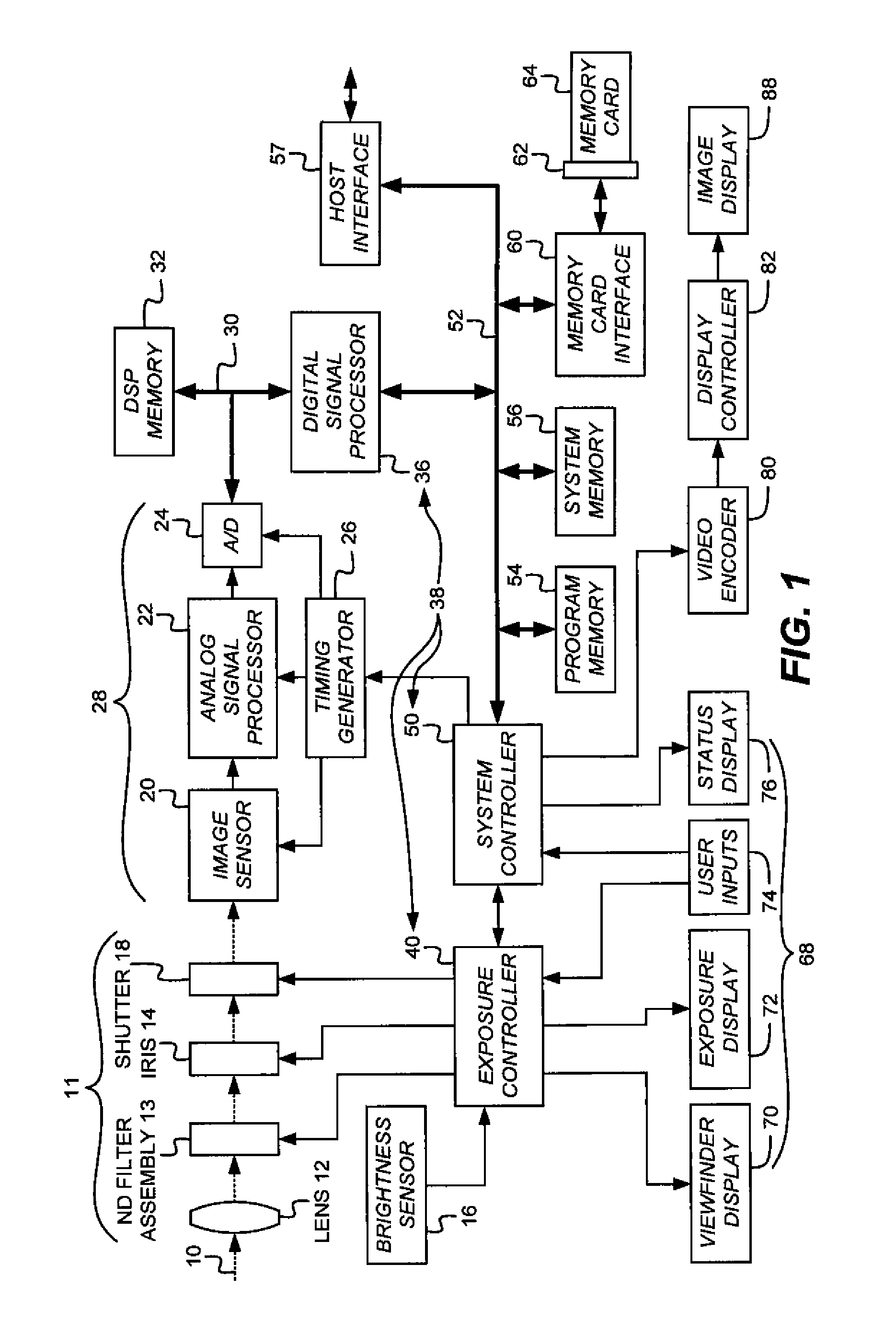
[0039]Turning now to FIG. 1, a block diagram of an image capture device shown as a digital camera embodying the present invention is shown. Although a digital camera will now be explained, the present invention is clearly a...


PUM


Abstract

A method for producing an improved high resolution image is disclosed including capturing low resolution images and a high resolution image; combining the low resolution images to provide an aggregate low resolution image; reducing the resolution of the high resolution image and then interpolated to produce a blurred high resolution image; calculating an image difference map using the aggregate high resolution image and blurred high resolution image; and using the image difference map along with the aggregate high resolution image and the high resolution image to produce an improved high resolution image.

Description

CROSS-REFERENCE[0001]Reference is made to commonly assigned U.S. patent application Ser. No. 12 / 184,446 filed Aug. 1, 2008 entitled METHOD FOR FORMING AN IMPROVED IMAGE USING IMAGES WITH DIFFERENT RESOLUTIONS, by John N. Border, et al., and U.S. patent application Ser. No. 12 / 550,559 filed Aug. 31, 2009 entitled USING CAPTURED HIGH AND LOW RESOLUTION IMAGES, by Aaron T. Deever, the disclosures of which are incorporated herein.FIELD OF THE INVENTION[0002]The invention pertains to generating an improved image from multiple images. More specifically, multiple images are used to form a high resolution image having reduced motion blur and reduced noise.BACKGROUND OF THE INVENTION[0003]A problem to be addressed is light deficient photography in the presence of motion during image capture causing motion blur in the image. The motion can be of a global variety where the entire scene being imaged moves together or of a local variety where one or more portions of the scene move at a different...

Claims


Application Information

Patent Timeline
Patent Type & Authority Patents(United States)
IPC IPC(8): H04N5/228G06K9/32H04N23/40
CPCG06T3/4053H04N5/23248H04N23/68
Inventor HAO, WEI
Owner MONUMENT PEAK VENTURES LLC
Learn More