
Sniffer leak detector

a leak detector and sniffer technology, applied in the direction of measuring devices, instruments, structural/machine measurement, etc., can solve the problems of gas detectors or vacuum pump apparatus destruction, pressure drop, and considerable pressure increase, so as to prevent contamination from entering the vacuum system

Active Publication Date: 2012-05-15
INFICON GMBH
View PDF17 Cites 10 Cited by
  • Summary
  • Abstract
  • Description
  • Claims
  • Application Information

AI Technical Summary

Benefits of technology

The detector described in this patent has a gas inlet conduit with a flow restrictor that prevents gas from flowing through when the hose coupling is detached. This prevents damage to the gas detector and vacuum pump apparatus in case of detachment. The flow restrictor has a negligible effect on the overall resistance during normal operation and is designed to choke and limit the flow when the sniffing line is detached. The detector can be easily switched off without the need for a valve and a filter is used to prevent contamination.

Problems solved by technology

This throttling is normally effected by the flow resistance of the sniffing line, which results in a pressure drop.
This will cause a considerable pressure increase in the high vacuum region, which may lead to destruction of the gas detector or the vacuum pump apparatus.
Thus, as result of a pressure increase, the emission filament of a mass spectrometer may be destroyed, with the consequence of total functional failure.
Also by a pressure increase in the forevacuum system, a turbomolecular pump is subjected to a considerable stress because, with the sniffing line detached, the pump has to work beyond the admissible specification.
A disadvantageous effect of the throttle is to be seen in that the blocking effect deteriorates with increasing length of the throttle capillary.

Method used


Image

  • Sniffer leak detector
  • Sniffer leak detector

Examples


Embodiment Construction

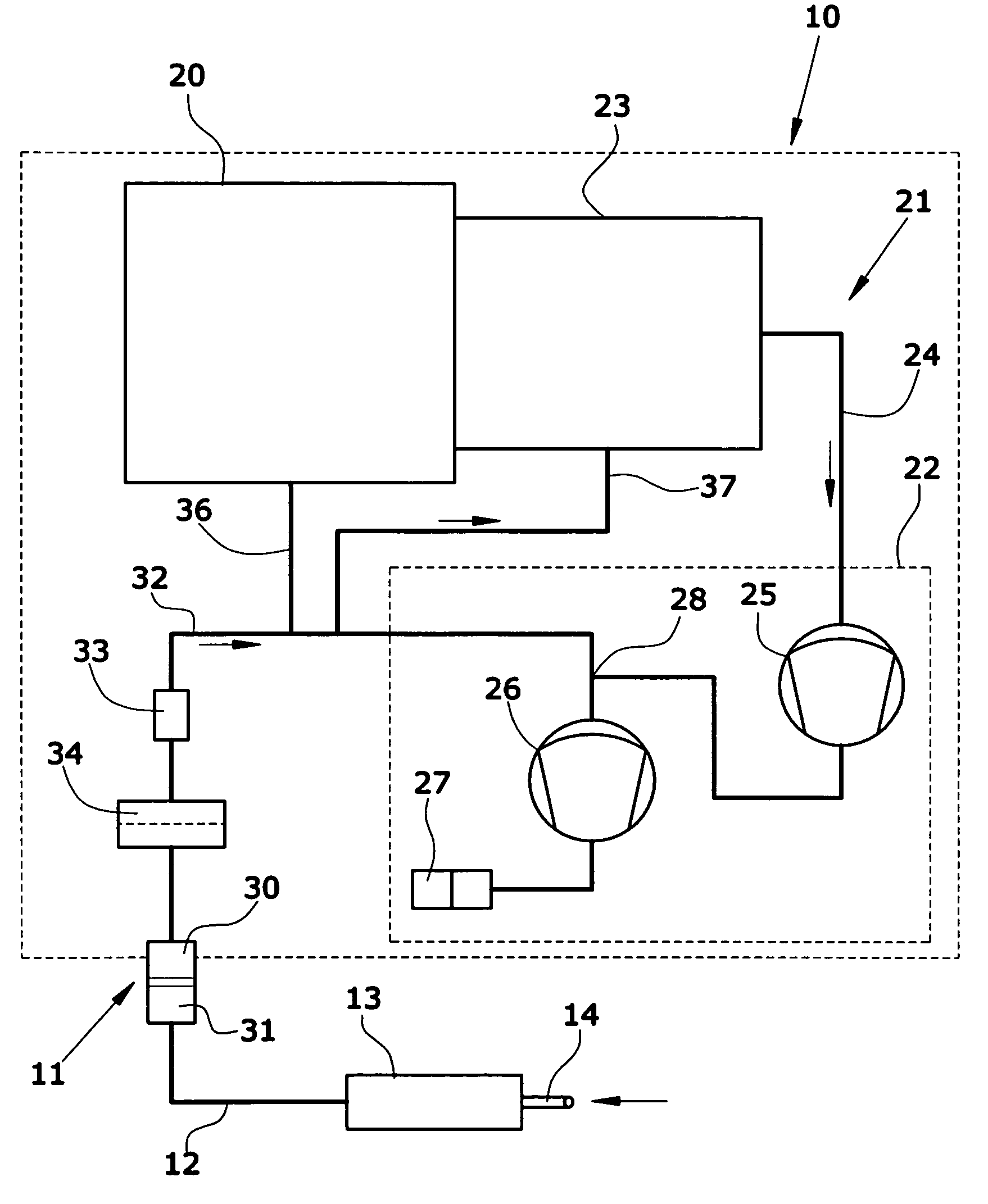
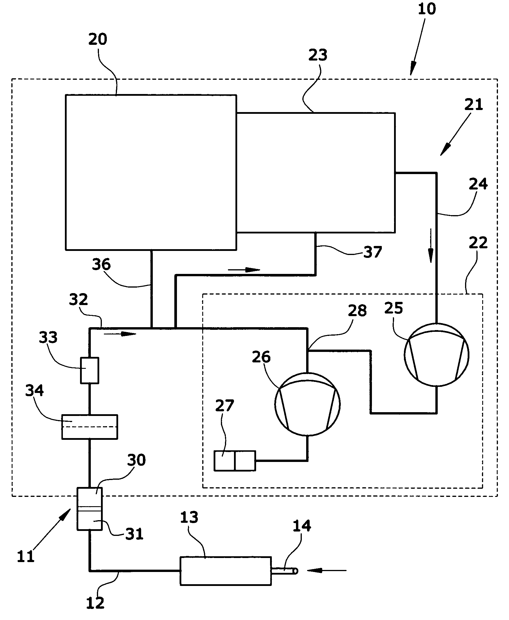
[0017]The sniffing leak detector comprises a main device 10 configured as a floor-supported device and accommodating the heavy components. Connected to said main device 10 via a hose coupling 11 is a flexible sniffing hose 12 provided with a hand-operated sniffing probe 13. Said sniffing probe 13 is operative to suck gas from the atmosphere via an inlet 14, which gas has to be tested for traces of the test gas, e.g. helium.

[0018]Main device 10 includes a gas detector 20 which in the present embodiment is a mass spectrometer. For the function of the mass spectrometer, a high vacuum is required which is generated by the vacuum pump device 21. The high vacuum is defined in that the pressure is p−3 mbar. The high vacuum region consists of an interior space of mass spectrometer 20.

[0019]Vacuum pump device 21 includes a forevacuum pump 22 and a turbomolecular pump 23 having its vacuum side connected directly to the housing of mass spectrometer 20.

[0020]The outlet of turbomolecular pump 23...


PUM


Abstract

A sniffing leak detector which comprises a mass spectrometer, a turbomolecular pump and a forevacuum pump. In case that the sniffing hose with the hand-operated sniffing probe becomes detached from the main device, atmospheric pressure would pass into the gas inlet conduit and disrupt the high vacuum in the mass spectrometer. In order to protect the mass spectrometer and the vacuum pump apparatus, a flow restrictor with an upstream filter is arranged in the gas inlet conduit.

Description

BACKGROUND[0001]1. Field of the Invention[0002]The disclosure relates to a sniffing leak detector comprising a main device including a vacuum pump apparatus generating a high vacuum, and a gas detector, and a hand-operated sniffing probe connected to a gas inlet conduit of the main device via a flexible sniffing hose, and a detachable hose coupling.[0003]2. Discussion of the Background Art[0004]In leak detectors of the type designed for sniffing operation, the gas taken up by the sniffing probe is conveyed via a sniffing line to the main device. Within the main device, the concentration of the test gas in the sucked airflow is measured with the aid of gas detector, e.g. a mass spectrometer. For analysis, only a small portion of the gas is admitted into the high vacuum where the gas analysis is performed by means of the mass spectrometer. The bulk of the gas flow is pumped directly back into the atmosphere by a forevacuum pump. Normally, the forevacuum pump also generates the low for...

Claims


Application Information

Patent Timeline
Patent Type & Authority Patents(United States)
IPC IPC(8): G01M3/16
CPCG01M3/205
Inventor WETZIG, DANIEL
Owner INFICON GMBH
Learn More