Inkjet recording device and inkjet recording method

a recording device and inkjet technology, applied in the direction of printing, inking apparatus, other printing apparatus, etc., can solve the problems of inability to easily spread ink on the recording material, generating voids or white stripes, and difficult to form solid parts, etc., to achieve the effect of reducing drive frequency, increasing the flow rate of ink drop, and maintaining ejection stability

Inactive Publication Date: 2015-06-16
KONICA MINOLTA INC
View PDF17 Cites 0 Cited by
  • Summary
  • Abstract
  • Description
  • Claims
  • Application Information

AI Technical Summary

Benefits of technology

[0017]The present invention can provide an inkjet recording device and an inkjet recording method that are capable of controlling a reduction in drive frequency, widening the dot diameter by increasing the flow rate of an ink drop while maintaining ejection stability when applied to a 3-cycle driving, by setting the pulse width of an expanded pulse and the negative pressure of a meniscus within predetermined ranges, and readily adjusting the flow rate corresponding to a recording material.

Problems solved by technology

For instance, when an image is formed on a non-absorbable recording material or a slightly absorbable recording material, an ink can fail to readily spread on a recording material.
Specifically, it is hard to form an image of a solid portion, thereby generating a void or a white stripe.

Method used


Image

  • Inkjet recording device and inkjet recording method
  • Inkjet recording device and inkjet recording method
  • Inkjet recording device and inkjet recording method

Examples


example 1 to 7

Comparative Example 1 to 3

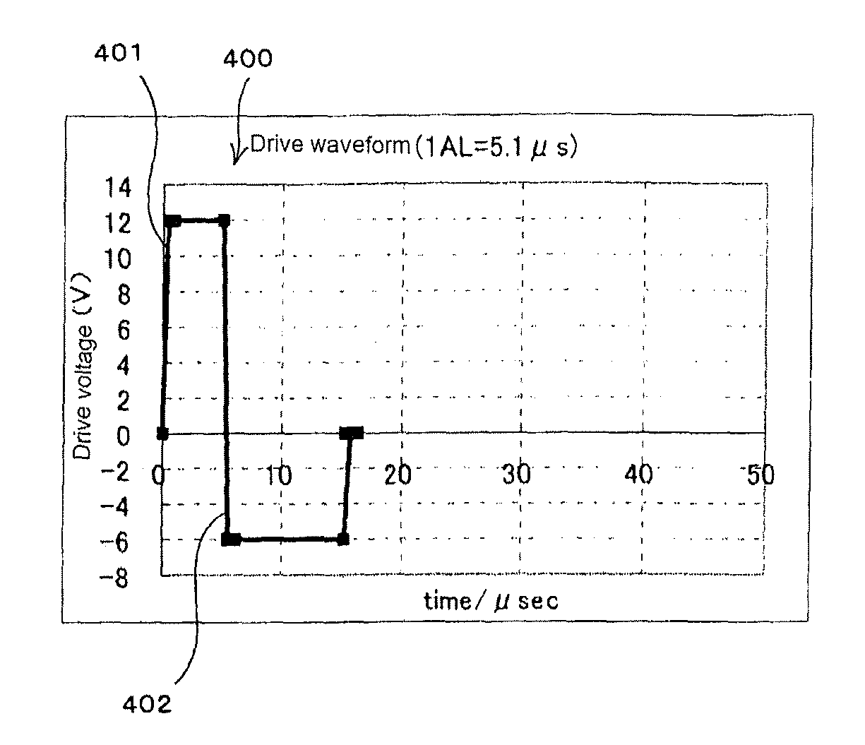
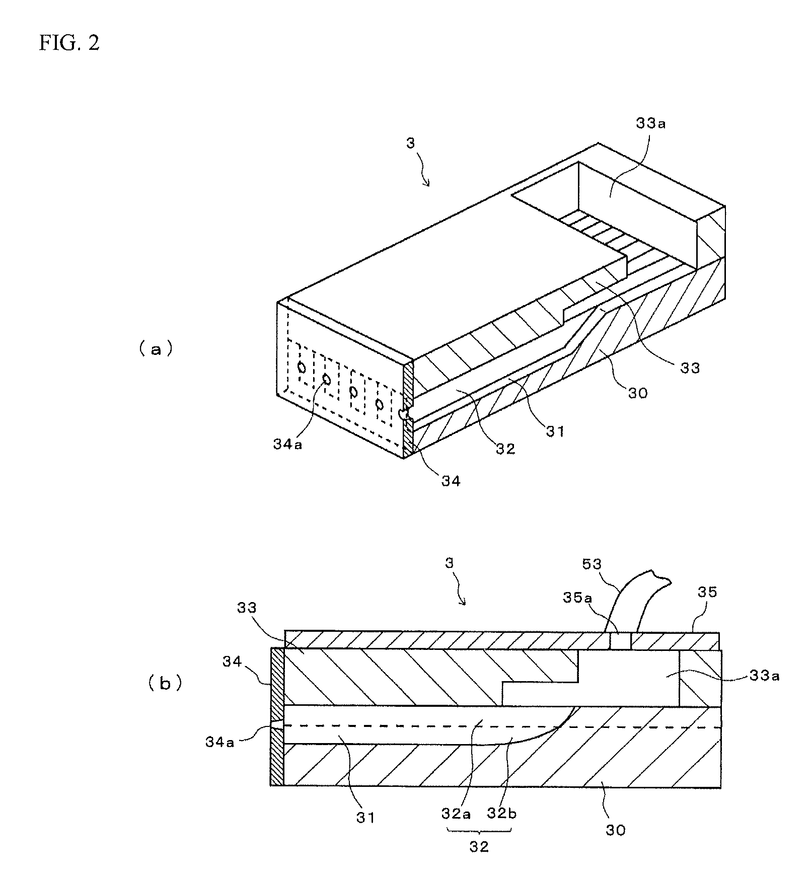
[0264]Using a sharing mode type record head (nozzle diameter: 27 μm, nozzle density: 360 dpi, distance between nozzle surface and recording material: 2 mm) like in FIG. 2, the record head was driven by 3-cycle driving method using a drive pulse composed of a square wave (1AL=5.1 μs, drive voltage ratio=|+Von / −Voff|=2 / 1) like in FIG. 4.

[0265]The pressure on a meniscus in nozzles was at −10 cmAq in all the Examples 1 to 7 and Comparative Examples 1 to 3, and each of the following evaluations was made when the pulse width W1 of a first drive pulse was changed as shown in Table 1 in Examples 1 to 7 and Comparative Examples 1 to 3.

[0266]The pulse width W2 of a second drive pulse was all 2AL, and the drive voltage of the first drive pulse +Von was adjusted as shown in Table 1 while each drive voltage ratio=|+Von / −Voff|=2 / 1 was maintained, so that the droplet speed after 0.5 mm flight from the nozzle surface was the speed shown in Table 1.

[0267]Evaluation 1: White...

example 8 to 12

Comparative Example 4 to 5

[0292]The record head was driven by 3-cycle driving method using a drive pulse composed of a square wave (1AL=5.1 μs, drive voltage ratio=|+Von / −Voff|=2 / 1) like in FIG. 4 by using the above sharing mode type record head (nozzle diameter: 27 μm, nozzle density: 360 dpi, distance between nozzle surface and recording material: 2 mm). Each ink used was ink 1.

[0293]The pulse width W1 of the first drive pulse was all fixed to 7.7 μs (=1.5AL), and when the pressure on the meniscus in the nozzles was changed as shown in Table 2 in Examples 8 to 12 and Comparative Examples 4 to 5, the following Evaluation 5 was performed in addition to said Evaluation 1: white stripe evaluation and said Evaluation 3: ejection stability evaluation to drive when even / odd nozzles are switched. In Evaluation 1, the drive voltage of the first drive pulse +Von was set while maintaining the drive voltage ratio=|+Von / −Voff|=2 / 1 so that the droplet speed after 0.5 mm flight from nozzle surfa...


PUM


Abstract

An inkjet recording device may include a plurality of pressure-generating chambers compartmented by walls including electromechanical conversion devices for generating a pressure; nozzles connected to the pressure-generating chambers; an ink supply portion; and a drive pulse generation device for driving said electromechanical conversion devices. The pressure-generating chambers may be separated into a plurality of groups. The pressure-generating chambers in each group may be driven in series so as to eject ink drops from said nozzles.

Description

[0001]This is the U.S. national stage of application No. PCT / JP2012 / 071044, filed on 21 Aug. 2012. Priority under 35 U.S.C. §119(a) and 35 U.S.C. §365(b) is claimed from Japanese Application No. 2011-183172, filed 24 Aug. 2011, the disclosure of which is also incorporated herein by reference.TECHNICAL FIELD[0002]The present invention relates to an inkjet recording device and an inkjet recording method.BACKGROUND[0003]Various types of inkjet heads are being proposed and developed, one of which is a sharing mode type inkjet head (Patent Documents 1 to 3).[0004]Specifically, the sharing mode type inkjet head ejects ink drops from nozzles connected to a plurality of pressure-generating chambers for generating a pressure by deforming walls composed of an electromechanical conversion means by operating the electromechanical conversion means that are compartmented by the walls.[0005]In recent years, there have been increasing needs for quickly forming an image on various types of media usi...

Claims


Application Information

Patent Timeline
Patent Type & Authority Patents(United States)
IPC IPC(8): B41J29/38B41J2/045
CPCB41J2/04581B41J2/04525B41J2/04588B41J2/04596B41J2202/10
Inventor FURUNO, KUMIKO
Owner KONICA MINOLTA INC
Why Eureka
Try Eureka