
Stator for an electric motor

a technology of stator and electric motor, which is applied in the direction of dynamo-electric machines, electrical equipment, magnetic circuit shapes/forms/construction, etc., can solve the problems of inability to achieve the effect of reducing the thickness of the stator sheet, reducing the thickness of the isthmus-like connecting pieces, and improving the efficiency and precision of the stepping motor

Active Publication Date: 2012-05-08
ETA SA MFG HORLOGERE SUISSE
View PDF10 Cites 0 Cited by
  • Summary
  • Abstract
  • Description
  • Claims
  • Application Information

AI Technical Summary

Benefits of technology

The invention is a stator design that reduces the transfer of magnetic flux between parts, making it simpler and less expensive to produce. This is achieved by reducing the thickness of the connecting sections in axial direction, which can be done using a stamping process. The stator is formed from three stator parts connected by three isthmus-like connecting sections, which are integrated into the stator body to further reduce production costs. The process for producing the stator is efficient and economical, and the stator is particularly useful in electric motors.

Problems solved by technology

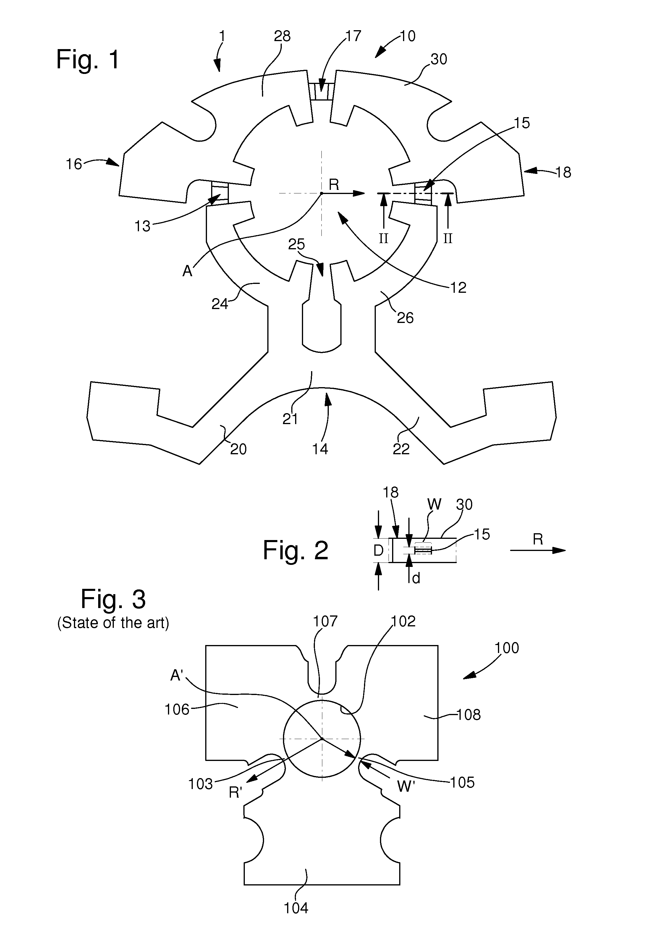
However, this interconnection of the stator parts 104, 106, 108 provided for mechanical reasons has the disadvantage that the wall thickness W of the webs 103, 105, 107 cannot be decreased as required for technical reasons (in particular because of the processing method), and therefore a residual magnetic flux is transferred between the stator parts 104, 106, 018.
In particular, if an electric motor provided with such a stator is configured as a stepping motor, this transfer of the residual magnetic flux between the stator parts can be so high that the efficiency and precision of the stepping motor is impaired.

Method used


Image

  • Stator for an electric motor
  • Stator for an electric motor

Examples


Embodiment Construction

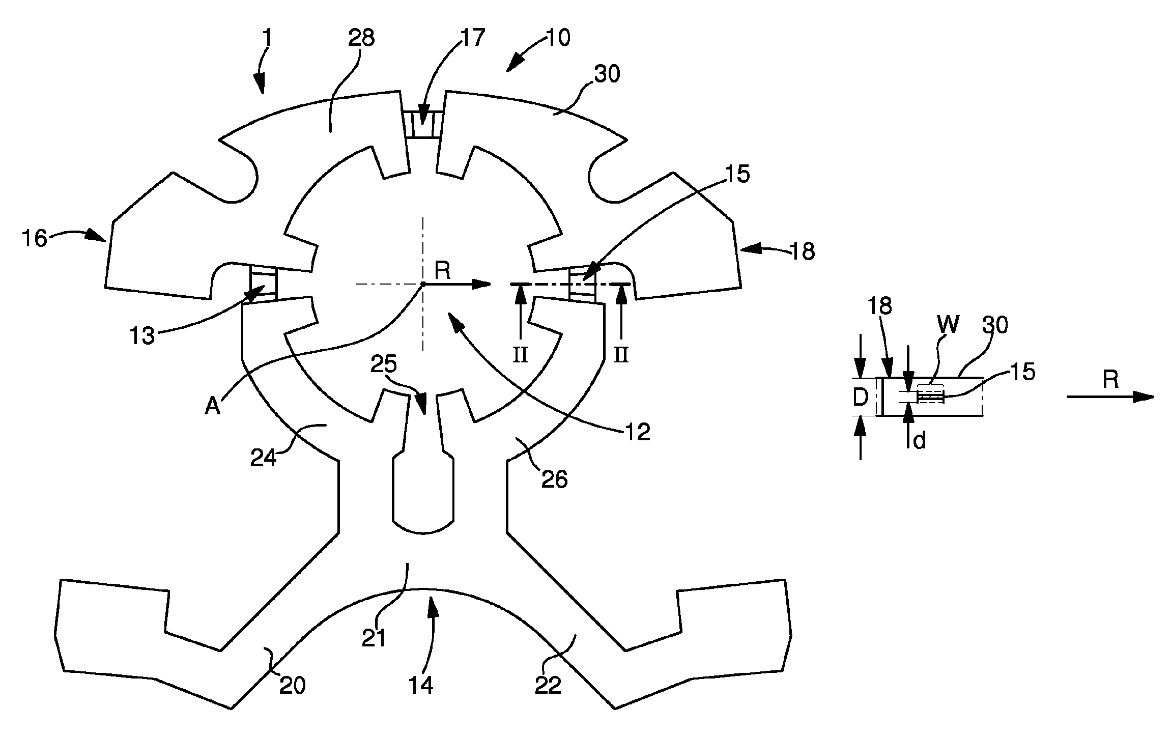
[0028]FIG. 1 shows the body 10 of a stator 1 in top view. For better understanding of the invention, the electrical windings of the stator are not shown. The stator body is produced from a stator sheet composed of an alloy of iron and silicon (FeSi) or an alloy or iron and nickel (FeNi).

The stator body 10 has a stator hole 12, which is configured to receive a rotor (not shown) so that the rotor and stator together form an electric motor with a motor housing (not shown).

[0029]The stator body 10 comprises three stator parts 14, 16, 18 that surround the stator hole 12. The lower stator part 14 has two arms 20, 22, which extend downwards on an angle and are connected to one another in the central region by means of a central section 21. A first coil receiving section 24 curved in a circular arc shape is provided that lies inside a first quadrant of the circular stator hole 12. A second coil receiving section 26 curved in a circular arc shape that lies inside a second quadrant of the cir...


PUM

PropertyMeasurementUnit
thicknessaaaaaaaaaa
thicknessaaaaaaaaaa
thicknessaaaaaaaaaa

Abstract

Disclosed is a stator for an electric motor, especially a stepping motor, comprising at least two stator parts (14, 16, 18) which jointly surround a stator hole (12) and are interconnected, connecting sections being provided for connecting the stator parts (14, 16, 18). The stator is characterized in that the connecting sections (13, 15, 17) are tapered relative to the adjacent sections of the adjoining stator parts (14, 16, 18) in an axial direction, parallel to the axis (A) of the stator hole (12), and form isthmi between the adjoining stator parts.

Description

[0001]This is a National Phase Application in the United States of International Patent Application No. PCT / EP2008 / 058603 filed Jul. 3, 2008, which claims priority on European Patent Application No. 07113728.5, filed Aug. 2, 2007. The entire disclosures of the above patent applications are hereby incorporated by reference.FIELD OF THE INVENTION[0002]The invention relates to a stator for an electric motor according to the preamble of claim 1. It also relates to a process for the production of the stator as well as an electric motor having this stator.BACKGROUND OF THE INVENTION[0003]A generic stator is generally known and illustrated in sectional view in FIG. 3. This known stator 100 has three stator parts 104, 106, 108, which surround a stator hole 102 and are connected to one another by means of webs 103, 105, 107. The webs 103, 105, 107 are thin-walled in radial direction R′ to the axis A′ of the stator hole 102 and have the same thickness in axial direction as the stator parts 10...

Claims


Application Information

Patent Timeline
Patent Type & Authority Patents(United States)
IPC IPC(8): H02K1/06
CPCH02K1/14Y10T29/49009
Inventor DREISBACH, OLAF
Owner ETA SA MFG HORLOGERE SUISSE
Learn More