
Recording apparatus and method for controlling the recording apparatus

a recording apparatus and recording technology, applied in the field of recording apparatus and controlling the recording apparatus, can solve the problems of increasing power consumption, increasing power consumption, and inability to switch to a power saving mode, so as to reduce power consumption without complicating the apparatus structure

Active Publication Date: 2012-05-01
CANON KK
View PDF11 Cites 4 Cited by
  • Summary
  • Abstract
  • Description
  • Claims
  • Application Information

AI Technical Summary

Benefits of technology

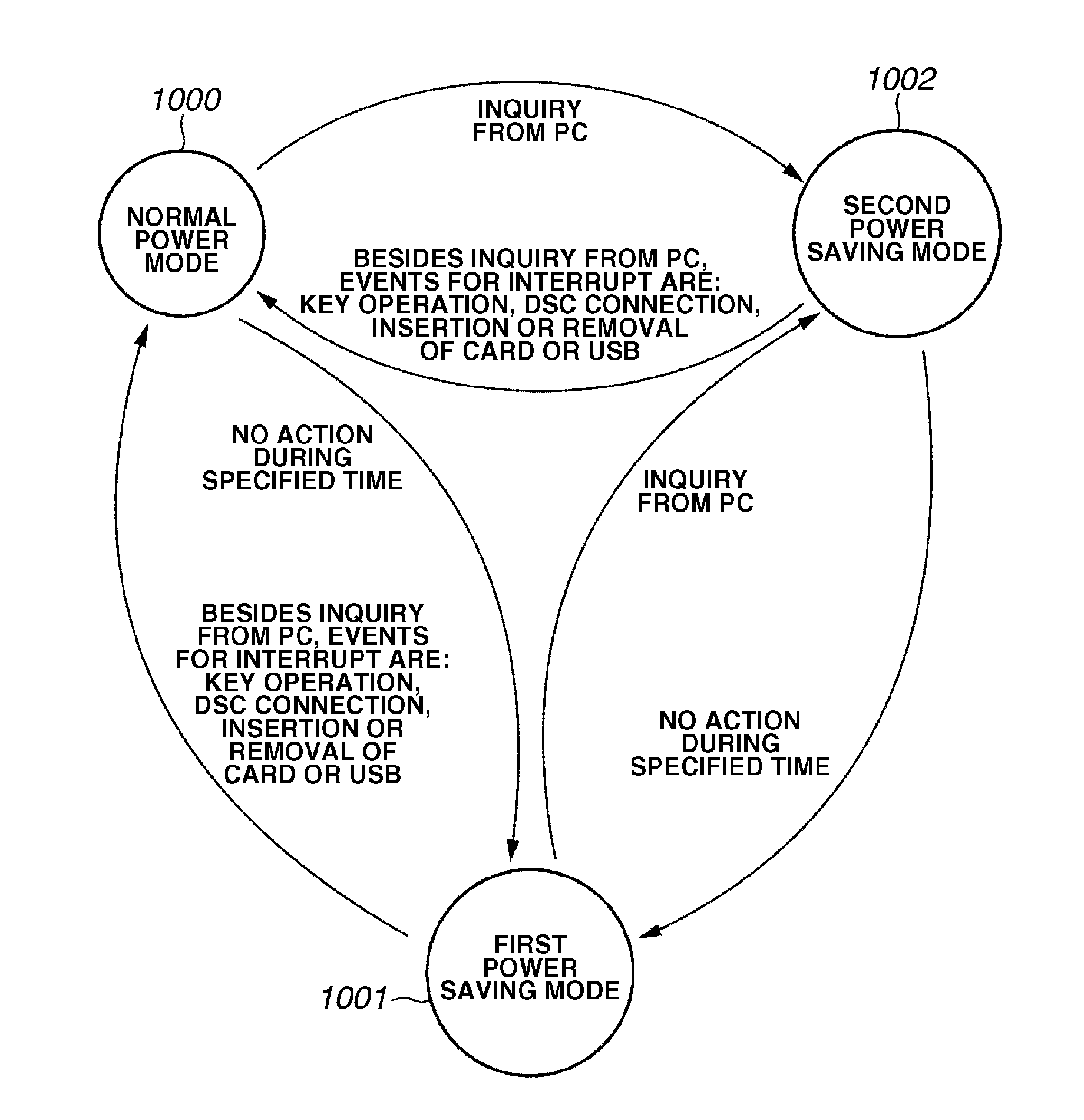
The present invention is about a recording apparatus that can save power while connected to a host computer. It includes a switching unit that switches between a power saving mode and a mode for responding to inquiries from the host computer. The recording apparatus has a memory card slot and a detection unit that detects the host computer's inquiries. A memory unit stores information to respond to the inquiries, and a notification unit notifies the host computer of the presence or absence of a memory card. This allows the recording apparatus to switch between the power saving modes and respond to the host computer's inquiries while reducing power consumption without complicating the apparatus structure or control method. The invention is useful for recording apparatuses that have a plurality of functions and need to minimize power consumption.

Problems solved by technology

However, in order to realize high-speed operation in response to the expanding functions in most advanced printers (e.g., MFPs), the internal clock has been made faster and electric power consumption is increasing.
However, in memory devices including a slot for mounting a storage function such as a memory card, there is a problem that when the recording apparatus is connected to a higher-level device (host PC), it may be impossible to switch to a power saving mode.
As a result of repeatedly making such transitions, power consumption increases or the life of electronic parts is shortened contrary to the saving efforts.
In Japanese Patent Laid-Open No. 2000-347762, clocks are continually supplied to specific peripheral circuits at all times. According to this configuration, even when the operation stops for a predetermined length of time, the clock cannot be stopped, and more reduction of power consumption cannot be realized.
Furthermore, in Japanese Patent Laid-Open No. 2003-110762, unless the power supply to the external devices connected to the main body is turned off, the transition to a power saving mode cannot be effected.
In the configuration shown in Japanese Patent Laid-Open No. 2006-31537, in order to shift from one power saving mode to another power saving mode, it is necessary to return once to the normal power consumption mode, which increases waste of electric power.
Moreover, since it is required to decide beforehand the power saving mode that is to be entered, control of the device becomes more complex.

Method used


Image

  • Recording apparatus and method for controlling the recording apparatus
  • Recording apparatus and method for controlling the recording apparatus
  • Recording apparatus and method for controlling the recording apparatus

Examples


Embodiment Construction

[0029]Various exemplary embodiments, features, and aspects of the invention will be described in detail below with reference to the drawings.

Exemplary Embodiment

[0030]FIG. 1 is a block diagram schematically illustrating an MFP apparatus according to an embodiment of the present invention. In an MFP apparatus 100, a central processing unit (CPU) 101 serves as a system controller that controls the entire MFP apparatus. The CPU 101 also controls communication with a host device such as a personal computer, which is connected to the MFP apparatus 100. Furthermore, the CPU 101 detects various kinds of inquiry or command from the host device, and executes required processes. A read only memory (ROM) 102 stores control programs to be executed by the CPU 101 and an incorporate operating system (OS) program.

[0031]In an exemplary embodiment, the control programs stored in the ROM 102 perform software control for scheduling, task switching or the like under control of the incorporated OS store...


PUM


Abstract

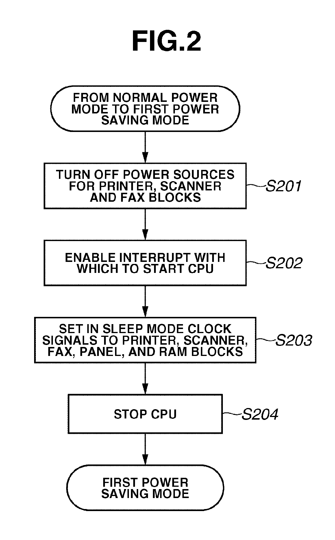
A recording apparatus can shift to power saving modes even when the recording apparatus is connected to the host PC, thus reducing power consumption. The recording apparatus can switch to a first power saving mode to supply power that enables detection of an inquiry from a host device and also switch to a second power saving mode to supply power that enables responding to an inquiry from the host device about information as to the memory card. Prior to switching to the first power saving mode, the recording apparatus stores information about a memory card attached to the card slot in a memory unit. In response to detection of an inquiry from the host device, the recording apparatus switches from the first power saving mode to the second power saving mode, and notifies information stored in the memory card controller to the host device.

Description

BACKGROUND OF THE INVENTION[0001]1. Field of the Invention[0002]The present invention relates to a recording apparatus and a method for controlling the recording apparatus.[0003]2. Description of the Related Art[0004]In recent years, in devices that operate on supplied power, there has been strong requirement that power consumption should be reduced to decrease running cost and prevent environmental destruction.[0005]For example, to reduce power consumption, various devices are provided with a power source control unit that includes an automatic power-off function to turn off power supply when a preset time elapses. This is intended to cut down on wasteful power consumption at night when the devices and appliances are less frequently used.[0006]Multifunction printers (hereafter referred to as MFP) equipped with functions in addition to printing, such as a copy function and a fax function are now starting to positively comply with various energy conservation standards.[0007]However, ...

Claims


Application Information

Patent Timeline
Patent Type & Authority Patents(United States)
IPC IPC(8): G06F1/32
CPCH04N1/00885H04N1/00896H04N1/00204H04N1/00347H04N2201/0036H04N2201/0044H04N2201/0049H04N2201/0051H04N2201/0087H04N2201/0094
Inventor NAKAMURA, TAKESHI
Owner CANON KK
Learn More