Fuel cell stack structure

a technology of fuel cell stack and stack structure, which is applied in the direction of fuel cells, fuel cell grouping, cell components, etc., can solve the problems of single cell damage, local thermal stress, and inability to recover unburned gas, so as to improve startability and responsibility, reduce energy required for heating, and increase the total efficiency of operations

Inactive Publication Date: 2012-05-01
NISSAN MOTOR CO LTD
View PDF15 Cites 1 Cited by
  • Summary
  • Abstract
  • Description
  • Claims
  • Application Information

AI Technical Summary

Benefits of technology

[0006]Furthermore, in the above stack structure, for the purposes of improving startability and responsibility at the transient operation and reducing energy required for heating at the start to increase a total efficiency of operations including start and stop, or for the purpose of increasing stacking density of the stack to increase output density, the central sections of the cell plate and the separator plate are made thin in some cases to reduce heat capacity. However, the stack structure could be subject to creep deformation due to thermal stress caused by a difference in coefficient of thermal expansion between the central sections of the cell plate and the separator plate and the sealing members when the stack structure repeatedly increases and decreases in temperature. Accordingly, the gas sealability is reduced, or defects such as cracks occur in the single cells, thus reducing the durability and resistance to heat shock.
[0007]In the above stack structure, both fuel gas and air are supplied through the central sections of the cell plate and the separator plate. Accordingly, the fuel gas and air introducing openings need to have circular shapes which are most suitable to keep the gas-tightness, and moreover the fuel and air introducing openings need to be individually sealed. Accordingly, the proportion of an area occupied by the central section to that of each cell plate becomes large, and the effective power generation area of the cell plate becomes small. Moreover, the sealing members are provided for long distance.
[0010]The present invention was made in the light of the problems of the conventional art, and an object thereof is to provide a fuel cell stack structure in which unburned fuel can be recovered and the gas sealability is hardly deteriorated to provide high reliability even under conditions where the stack temperature frequently varies such as at the start and stop, the transient operation, or the like. Another object of the present invention is to provide a fuel cell stack structure in which the heat shock resistance can be increased while the cell plate and the separator plate are reduced in thickness for low heat capacity and moreover the output density can be increased.

Problems solved by technology

In the case of the fuel cell stack structure of U.S. Pat. No. 6,344,290, both gases of fuel gas and air are supplied through central sections of cell plates and separator plates and exhausted through outer peripheries, and thus unburned gas cannot be recovered.
Furthermore, in such a case, unstable combustion in the outer periphery causes local thermal stress in single cells, and the single cells could be damaged.
However, the stack structure could be subject to creep deformation due to thermal stress caused by a difference in coefficient of thermal expansion between the central sections of the cell plate and the separator plate and the sealing members when the stack structure repeatedly increases and decreases in temperature.
Accordingly, the gas sealability is reduced, or defects such as cracks occur in the single cells, thus reducing the durability and resistance to heat shock.

Method used


Image

  • Fuel cell stack structure
  • Fuel cell stack structure
  • Fuel cell stack structure

Examples


Embodiment Construction

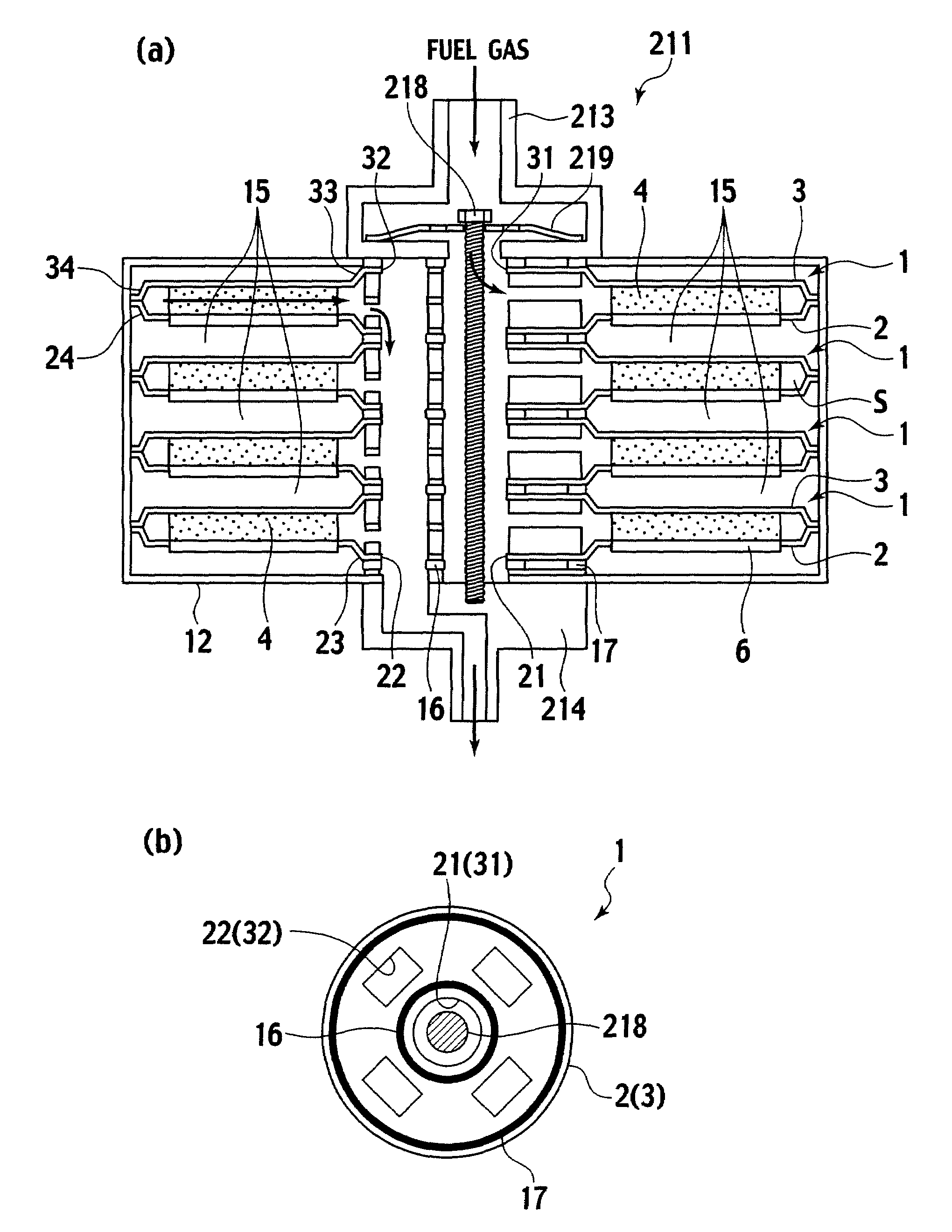
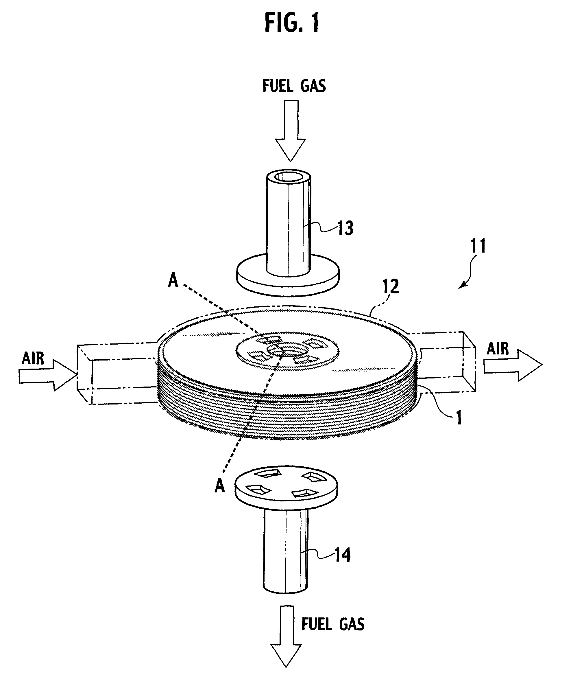
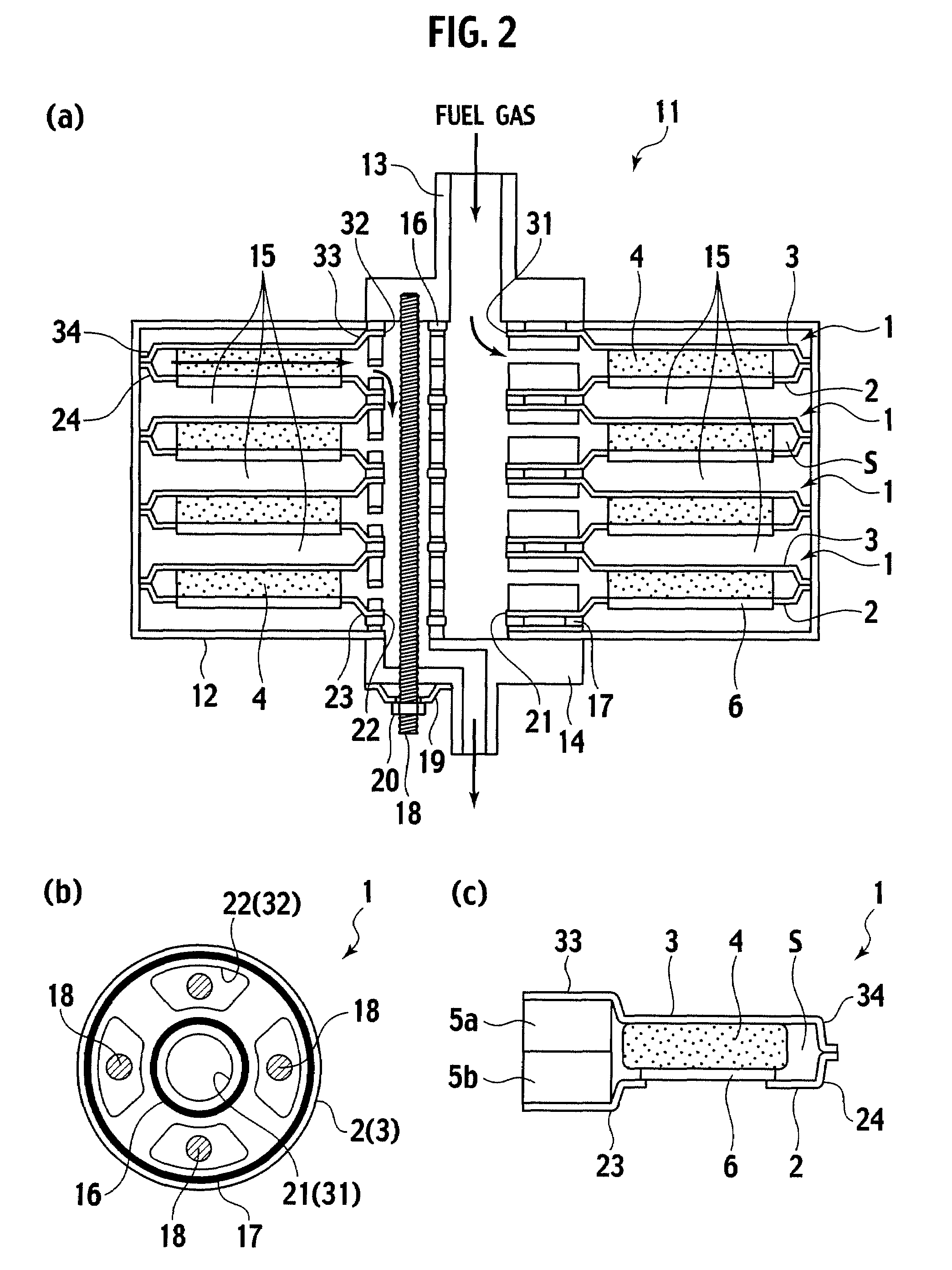
[0021]A fuel cell stack structure (hereinafter, also referred to as just a stack structure) of the present invention is composed of a plurality of solid oxide fuel cells (hereinafter, also referred to as just fuel cells) which are stacked facing a same direction. Each of the fuel cells includes a separator plate and a cell plate joined to each other. The cell plate is circular, holds single cells, and has a gas introducing opening and a gas exhausting opening in a central section thereof. The separator plate is circular and has a gas introducing opening and a gas exhausting opening in a central section thereof. An outer peripheral edge of the separator plate is joined to an outer peripheral edge of the cell plate.

[0022]Furthermore, at least one of the cell plate and the separator plate includes a step along the outer peripheral edge thereof, and the step forms a space between the cell plate and the separator plate.

[0023]In between the central sections of the cell plate and the separ...


PUM

PropertyMeasurementUnit
thicknessaaaaaaaaaa
outer diameteraaaaaaaaaa
step sizesaaaaaaaaaa

Abstract

Solid oxide fuel cells each include a circular cell plate holding single cells as a solid oxide fuel cells and having a gas introducing opening and a gas exhausting opening in a central section. A circular separator plate has a gas introducing opening and a gas exhausting opening in a central section. Sealing members allow the gas intruding openings of the cell plate and the separator plate to airtightly communicate with each other and allow the gas exhausting openings of the cell plate and the separator plate to airtightly communicate with each other.

Description

[0001]This is a 371 national phase application of PCT / JP2006 / 321327, filed Oct. 26, 2006, which claims priority to Japanese Patent Application No. JP 2005-314932, filed Oct. 28, 2005, and Japanese Patent Application No. JP 2006-264443, filed Sep. 28, 2006.TECHNICAL FIELD[0002]The present invention relates to a fuel cell stack structure composed of a plurality of solid oxide fuel cells stacked.BACKGROUND ART[0003]Conventional fuel cell stack structures each composed of a plurality of solid oxide fuel cells stacked are disclosed by U.S. Pat. No. 6,344,290 and Japanese Patent Unexamined Publication No. 2002-151106.DISCLOSURE OF INVENTION[0004]In the case of the fuel cell stack structure of U.S. Pat. No. 6,344,290, both gases of fuel gas and air are supplied through central sections of cell plates and separator plates and exhausted through outer peripheries, and thus unburned gas cannot be recovered. Accordingly, in the case where the gas flow varies, such as at transient operation, the...

Claims


Application Information

Patent Timeline
Patent Type & Authority Patents(United States)
IPC IPC(8): H01M8/24H01M2/08
CPCH01M8/0247H01M8/04097H01M8/243H01M8/248H01M2008/1293Y02E60/50Y02E60/525H01M8/2432H01M8/2483
Inventor KUSHIBIKI, KEIKONAKAJIMA, YASUSHIIBUKA, SHIGEOKOMATSU, HIROKAZUYAGUCHI, TATSUYA
Owner NISSAN MOTOR CO LTD
Why Eureka
Try Eureka