
Method and circuit for providing RF isolation of a power source from an antenna and an RFID device employing such a circuit

a technology of rf isolation and power source, which is applied in the direction of resonant antennas, antenna couplings, instruments, etc., can solve the problems that the method may not be effective, the impedance of the battery and/or the metallic parts of the battery may affect the rf section of the device,

Inactive Publication Date: 2012-04-24
POWERID LTD
View PDF30 Cites 0 Cited by
  • Summary
  • Abstract
  • Description
  • Claims
  • Application Information

AI Technical Summary

Benefits of technology

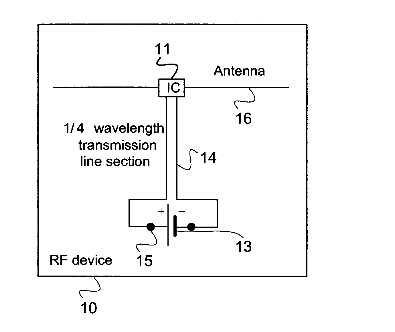
[0011]The term ‘RF isolate’ as used herein with respect to some embodiments, refers to eliminating or reducing the effect of low battery impedance on the radio frequency of a device. Specifically, the transmission line isolates the balanced RF components from the power source so that the power source does not degrade the performance of the balanced RF components.
[0013]In some embodiment of the present invention a section of quarter wavelength transmission line or odd multiple sections of quarter wavelength, at operating frequency of the RFID transponder is used to connect the battery to the ASIC and the antenna. In an exemplary embodiment of the invention, the quarter wavelength transmission line converts the low RE impedance of the battery into high impedance at the antenna and ASIC end and provides a desired RE isolation between the battery, the antenna and the ASIC, and optionally prevents deterioration of the antenna performance. In an exemplary embodiment of the invention, the transmission line conductors present negligible resistance to the direct current of the battery and do not effect the battery operation.
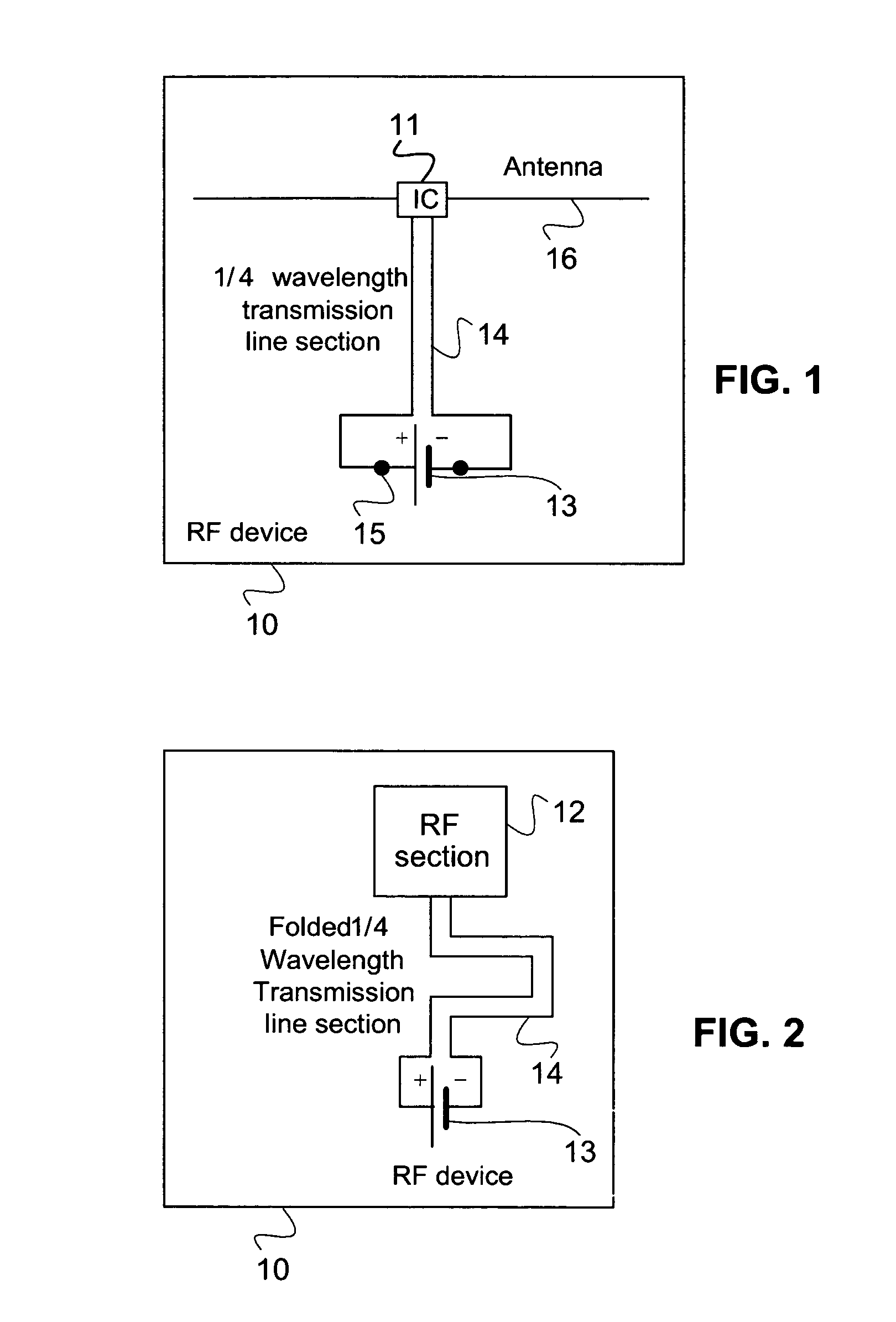
[0014]In some embodiments, the quarter wavelength section is folded to minimize the space required. Odd multiple quarter wavelength sections may be used, for example, for larger distance between the battery and the RFID ASIC.
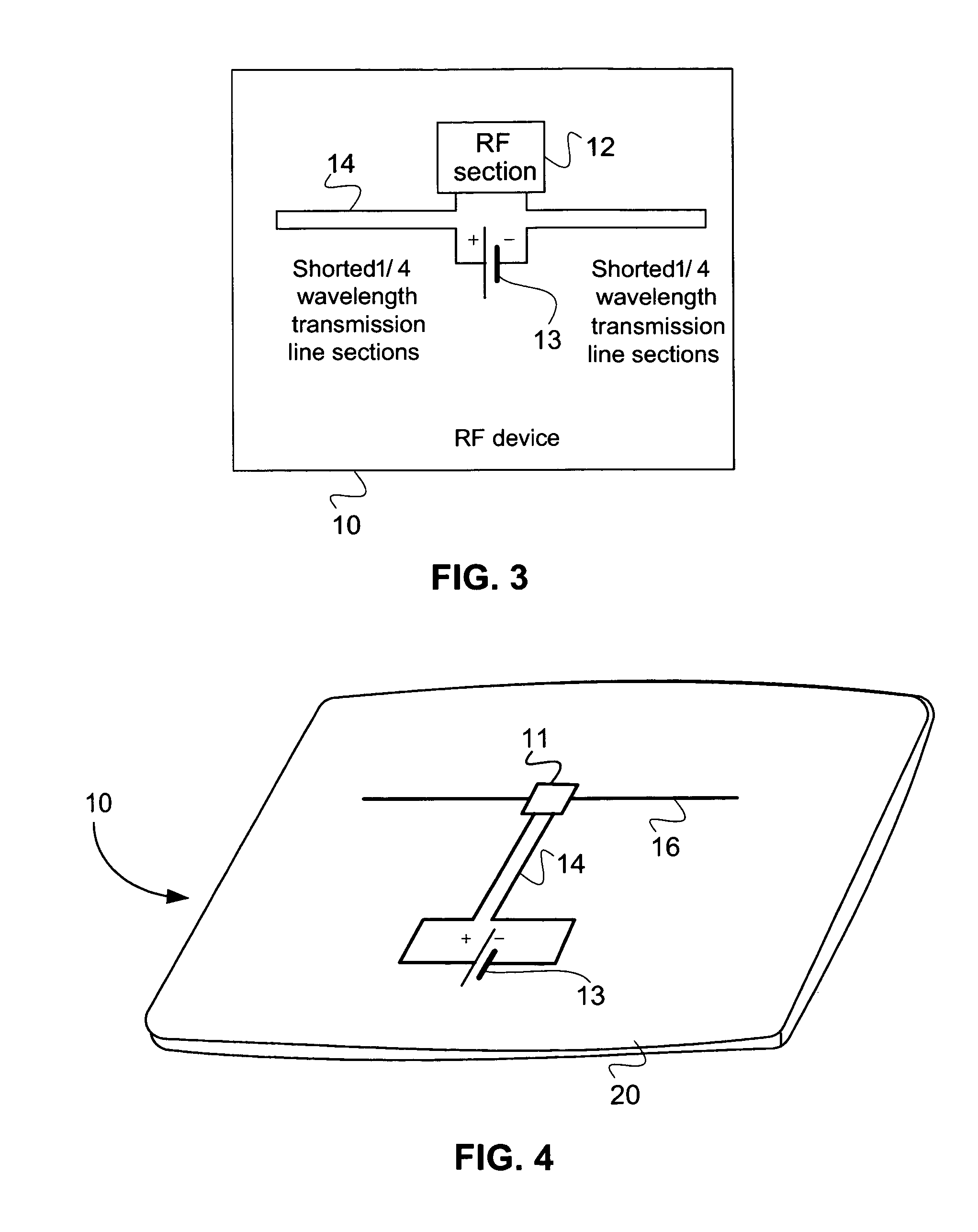
[0016]Optionally, multiple shorted quarter wavelength sections are provided. Optionally, the sections each have different wavelengths (e.g., 3%, 5%, 10% or 15% different), so as to provide a greater isolation bandwidth for the RFID device.

Problems solved by technology

A problem associated with RF devices which include an RF section and a power source, is that the battery impedance and / or battery metallic parts may affect the RF section of the device.
However, in certain battery operated radio frequency devices, wherein the antenna cannot be easily redesigned or wherein the device is thin and flexible, these methods may not be effective.

Method used


Image

  • Method and circuit for providing RF isolation of a power source from an antenna and an RFID device employing such a circuit
  • Method and circuit for providing RF isolation of a power source from an antenna and an RFID device employing such a circuit
  • Method and circuit for providing RF isolation of a power source from an antenna and an RFID device employing such a circuit

Examples


Embodiment Construction

[0062]In the following description of different embodiments of the invention, identical or similar reference numerals will generally be used to refer to identical components or to components that fulfill a common function.

[0063]FIG. 1 shows a schematic representation of a device 10 according to one embodiment of the present invention. As can be seen from FIG. 1, the device includes electronic circuitry 1, such as an integrated circuit which includes a RF section 12 (shown in FIG. 2), at least one power source which may include a battery 13 and an isolation circuit 14 to RF isolate the at least one power source. Optionally, the power source 13 may be removably coupled to the isolation circuit 14 by respective power connectors 15. In some embodiments, device may include an antenna 16.

[0064]The isolation circuit 14 that is used to RF isolate the power source 13 may include an open quarter wavelength transmission line section. Examples of quarter wavelength transmission line section inc...


PUM


Abstract

An RFID device including:electronic circuitry suitable for an RFID device comprising a radio frequency section;an antenna;a battery which provides the device with power; andat least one quarter wavelength transmission line coupled between the battery and one or both of the electronic circuitry and the antenna.

Description

RELATED APPLICATIONS[0001]This application is a continuation-in-part of PCT Patent Application No. PCT / IL2007 / 001235 filed on Oct. 16, 2007, which claims the benefit of priority of U.S. Provisional Patent Application No. 60 / 829,780 filed on Oct. 17, 2006.[0002]This application is also a continuation-in-part of U.S. patent application Ser. No. 11 / 872,928 filed on Oct. 16, 2007, which claims the benefit of priority of U.S. Provisional Patent Application No. 60 / 829,780 filed on Oct. 17, 2006.[0003]The disclosures of the above applications are incorporated herein by reference.FIELD OF THE INVENTION[0004]The present invention, in some embodiments thereof, relates in general to an RF device, and in particular to battery operated RF devices, such as RFID devices.BACKGROUND OF THE INVENTION[0005]There are many examples of battery operated radio frequency (RF) devices, such as RF Short Range Devices (SRD), RF Automatic Meter Reading (AMR) devices, active RFID devices and battery assisted pas...

Claims


Application Information

Patent Timeline
Patent Type & Authority Patents(United States)
IPC IPC(8): G06K19/06
CPCG06K19/07749H01Q1/2225H01Q1/52
Inventor NITZAN, ZVILAVEE, DORONALMOG, BENYAMIN
Owner POWERID LTD
Learn More