Delay chain burn-in for increased repeatability of physically unclonable functions

a delay chain and repeatability technology, applied in the field of physical unclonable functions, can solve the problems of unique and unpredictable ways, logic functions implemented by the circuit, and difficult characterization and cloning of electrical circuit functions, and achieve the effects of increasing the repeatability of physically undetectable functions (pufs), enhancing the variation of signal delay, and increasing the turn on voltag

Inactive Publication Date: 2012-04-17
INT BUSINESS MASCH CORP
View PDF3 Cites 16 Cited by
  • Summary
  • Abstract
  • Description
  • Claims
  • Application Information

AI Technical Summary

Benefits of technology

[0006]The disclosure is directed to a circuit and method for increasing the repeatability of physically undetectable functions (PUFs) by enhancing the variation of signal delay through two delay chains during chip burn-in. A burn-in circuit is used to hold the inputs of the two delay chains at opposite random values during the burn-in process such that one delay chain is held at one random state and the other delay chain is held at the opposite random state. All the PFETs in the delay chains with a low value at the input will be burned in with a higher turn on voltage due to the known phenomenon of Negative Biased Temperature Instability (NBTI). Since the PFETs affected in the two delay chains are driven by opposite transitions at burn-in, alternating sets of delay components in the two delay chains are affected by the burn-in cycle. Under normal operation, both of the delay chains see the same input so only one chain has an increase in delay to achieve a statistically reliable difference in the two delay paths thereby increasing the overall repeatability of the PUF circuit.

Problems solved by technology

A PUF is an electrical circuit function that is difficult to characterize and clone.
Each PUF device has a unique and unpredictable way of mapping challenges to responses.
When a circuit with the same layout mask is fabricated on different chips, the logic function implemented by the circuit is different for each chip due to the random variations of delays.
If the random process variation does not cause a statistically reliable difference in the delay of the paths, then the PUF will have low repeatability.
This means that variation in temperature, voltage, and other factors can change the response of the system and thus the challenge response of the circuit will not be useful due to low repeatability.

Method used


Image

  • Delay chain burn-in for increased repeatability of physically unclonable functions
  • Delay chain burn-in for increased repeatability of physically unclonable functions
  • Delay chain burn-in for increased repeatability of physically unclonable functions

Examples


Embodiment Construction

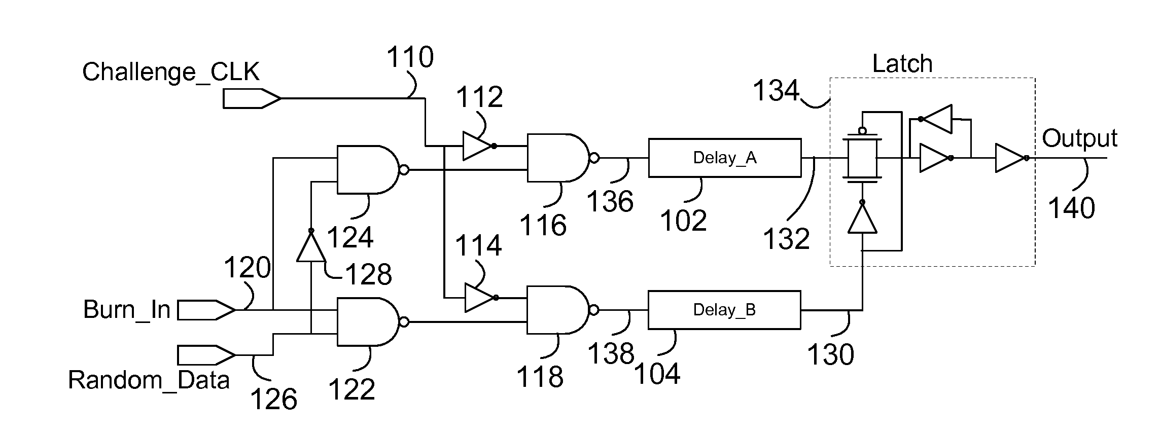
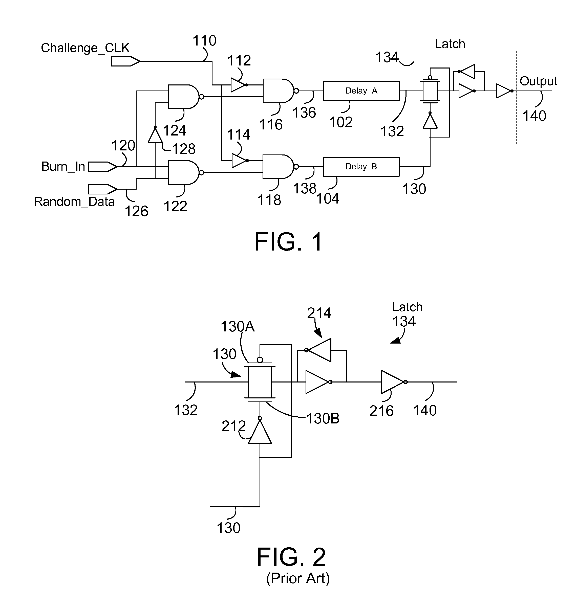
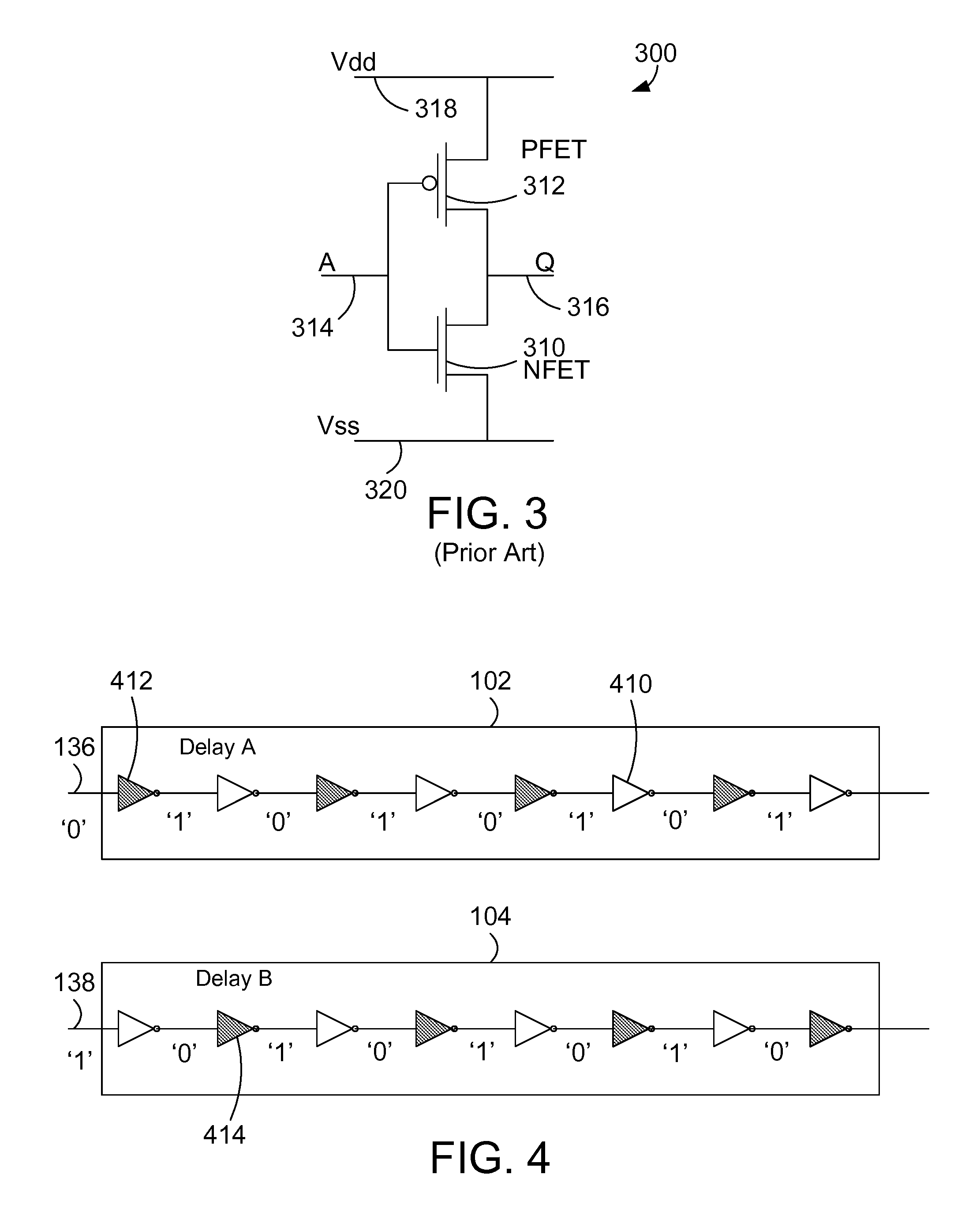
[0015]Described herein is an apparatus and method for increasing the repeatability of physically undetectable functions (PUFs) by enhancing the variation of signal delay through two delay chains during chip burn-in. A burn-in circuit is used to hold the inputs of the two delay chains at opposite random values during the burn-in process such that one delay chain is held at one random state and the other delay chain is held at the opposite random state. All the PFETs in the delay chains with a low value at the input will be burned in with a higher turn on voltage due to the known phenomenon of Negative Biased Temperature Instability (NBTI). Since the PFETs affected in the two delay chains are driven by opposite transitions at burn-in, alternating sets of delay components in the two delay chains are affected by the burn-in cycle. Under normal operation, both of the delay chains see the same input so only one chain has an increase in delay to achieve a statistically reliable difference ...


PUM


Abstract

A circuit and method increases the repeatability of physically undetectable functions (PUFs) by enhancing the variation of signal delay through two delay chains during chip burn-in. A burn-in circuit holds the inputs of the two delay chains at opposite random values during the burn-in process. All the PFETs in the delay chains with a low value at the input will be burned in with a higher turn on voltage. Since the PFETs affected in the two delay chains are driven by opposite transitions at burn-in, alternating sets of delay components in the two delay chains are affected by the burn-in cycle. Under normal operation, both of the delay chains see the same input so only one chain has an increase in delay to achieve a statistically reliable difference in the two delay paths thereby increasing the overall repeatability of the PUF circuit.

Description

BACKGROUND[0001]1. Technical Field[0002]This disclosure generally relates to physically unclonable functions, and more specifically relates to burn-in of delay chains for increased repeatability of physically unclonable functions.[0003]2. Background Art[0004]For security reasons, it is desirable to implement physically unclonable functions (PUF) in integrated circuits. A PUF is an electrical circuit function that is difficult to characterize and clone. A PUF is useful for challenge-response authentication type security in electronic systems. The PUF can be used in electronic systems to obtain different functions or security keys in two chips where the differences in the two chips are physically undetectable. Each PUF device has a unique and unpredictable way of mapping challenges to responses.[0005]A silicon or physical PUF exploits random variations in a circuit produced during the manufacturing of the circuit device. The PUF circuit can use these random variations in the delay of ...

Claims


Application Information

Patent Timeline
Patent Type & Authority Patents(United States)
IPC IPC(8): H03K19/00G06F11/30G06F13/00
CPCG06F7/588H04L9/0866
Inventor BEHRENDS, DERICK GARDNERCHRISTENSEN, TODD ALANHEBIG, TRAVIS REYNOLDNELSON, DANIEL MARK
Owner INT BUSINESS MASCH CORP
Why Eureka
Try Eureka