Brush assembly with molded brush sleeve

a technology of molded brushes and sleeve, which is applied in the direction of packaging foodstuffs, packaging goods, manufacturing tools, etc., can solve the problems of reducing the crispness of the application process, reducing the adaptability of twisted wire constructions to different materials and application goals, and reducing the precision of the application process. , to achieve the effect of optimizing eyelash loading, combing characteristics, and application

Active Publication Date: 2012-04-10
HCP PACKAGING USA
View PDF39 Cites 13 Cited by
  • Summary
  • Abstract
  • Description
  • Claims
  • Application Information

AI Technical Summary

Benefits of technology

[0011]An object of embodiments of the invention is to provide a manufacturing technique and a brush assembly produced thereby that optimize eyelash loading, application, and combing characteristics to enable the achievement of a finished appearance expeditiously in as few strokes and as few introductions of the applicator brush assembly into the mascara reservoir as possible.
[0012]A further object of particular constructions of the invention is to provide a construction method and resulting brush assembly that allow bristles to be spaced in an even geometrical array to permit superior product loading of the bristles, superior product payoff onto the eyelashes, and superior defining and lengthening characteristics.
[0013]A related object of embodiments of the invention is to provide a mascara brush assembly and method for producing the same that enables the optimal application of makeup onto lashes so that they are optimally loaded, separated, and lengthened providing an enhanced, volumized, defined, and long eyelash look.
[0014]Another object of certain embodiments of the invention is to provide a molded brush sleeve with spaced, soft bristles for assembly with a generally rigid support to produce a stable yet pliable applicator. A further object of embodiments of the invention is to provide a brush sleeve for an applicator brush that is molded with bristles spaced and aligned to provide channels for eyelashes to pass through thereby to improve the retention of product and the transfer of the same onto eyelashes.
[0019]Under some constructions of the invention, the bristles of the brush sleeve can have a diamond-shaped cross section to improve product loading and payoff. In such embodiments, the bristles can be oriented in relation to the tubular core member with first and second opposed corners longitudinally aligned in relation to the core member and third and fourth opposed corners circumferentially aligned in relation to the core member. Further, the bristles can be disposed in symmetrical rows spaced radially around the core member, and they can be longitudinally aligned in symmetrical columns along the core member.
[0021]In alternative embodiments, a support stem can comprise a distal portion of the applicator rod, and the rod hole can be formed in a distal end of the support stem. The brush sleeve can thus be slidably received onto the support stem and retained by the rivet inserted into the rod hole. The support stem can have circular or non-circular cross sections and, additionally or alternatively, arcuate longitudinal profiles to induce the brush sleeve to pursue a like configuration. A peripheral retaining wall that that extends distally from a widened shoulder at the proximal end of the support stem can again receive and protect the proximal portion of the brush sleeve.

Problems solved by technology

Although they have varied in the shape and material composition of the bristles, wires, and the resulting contouring of the brush, twisted wire constructions are limited in their adaptability to different materials and application goals.
The bristles in a twisted wire configuration necessarily tend to follow the helical pattern of the twisted wire core, and precise control over the location and orientation of the bristles is substantially impossible.
Furthermore, mascara is trapped in the gaps between the bristles thereby reducing the crispness of the application process and establishing a haven for the accumulation of debris and other impurities leading to an undesirable result know as clumping of the product.
Still further, the creation of a twisted wire arrangement is an inherently complex process having complicated processing and machinery requirements.
Unfortunately, while the resulting brushes may have had some effectiveness when initially developed, increases in viscosity and other modifications to mascara compositions have rendered such designs less than ideal.
For example, their soft bristles can collapse when confronted with modern high viscosity mascara.
Unfortunately, while the soft elastomeric material may be preferable for the projecting bristles, forming the support from that same material can yield a brush that is excessively flexible such that it can bend and wobble during use thereby harming the application process.
As a result, the sleeve and the core are fixed in relation to one another such that the resulting cross section and longitudinal profiles of the sleeve are unchangeable.
Moreover, with disparate materials fixed to one another, a dimensional change in one component in Weihrauch or Eckers et al., such as swelling of the soft bristle material due to prolonged exposure to somewhat harsh mascara products, can cause the sleeve and the core to separate leading to poor product performance and potential danger to the user.
Furthermore, where a sleeve is to be molded directly onto such a reinforcing core, the manufacturer is inherently limited in the cross-sectional and longitudinal profiles that can be achieved.
In addition to being limited to the one chosen shape, the possibilities in shape are in and of themselves inherently limited since the tooling used to produce such brush sleeves is highly complicated, particularly since the molded bristles protrude in several directions.
To accommodate the molding of the bristles, the molding tool must be designed to open in multiple directions thereby imposing substantial design limitations.

Method used


Image

  • Brush assembly with molded brush sleeve
  • Brush assembly with molded brush sleeve
  • Brush assembly with molded brush sleeve

Examples


Embodiment Construction

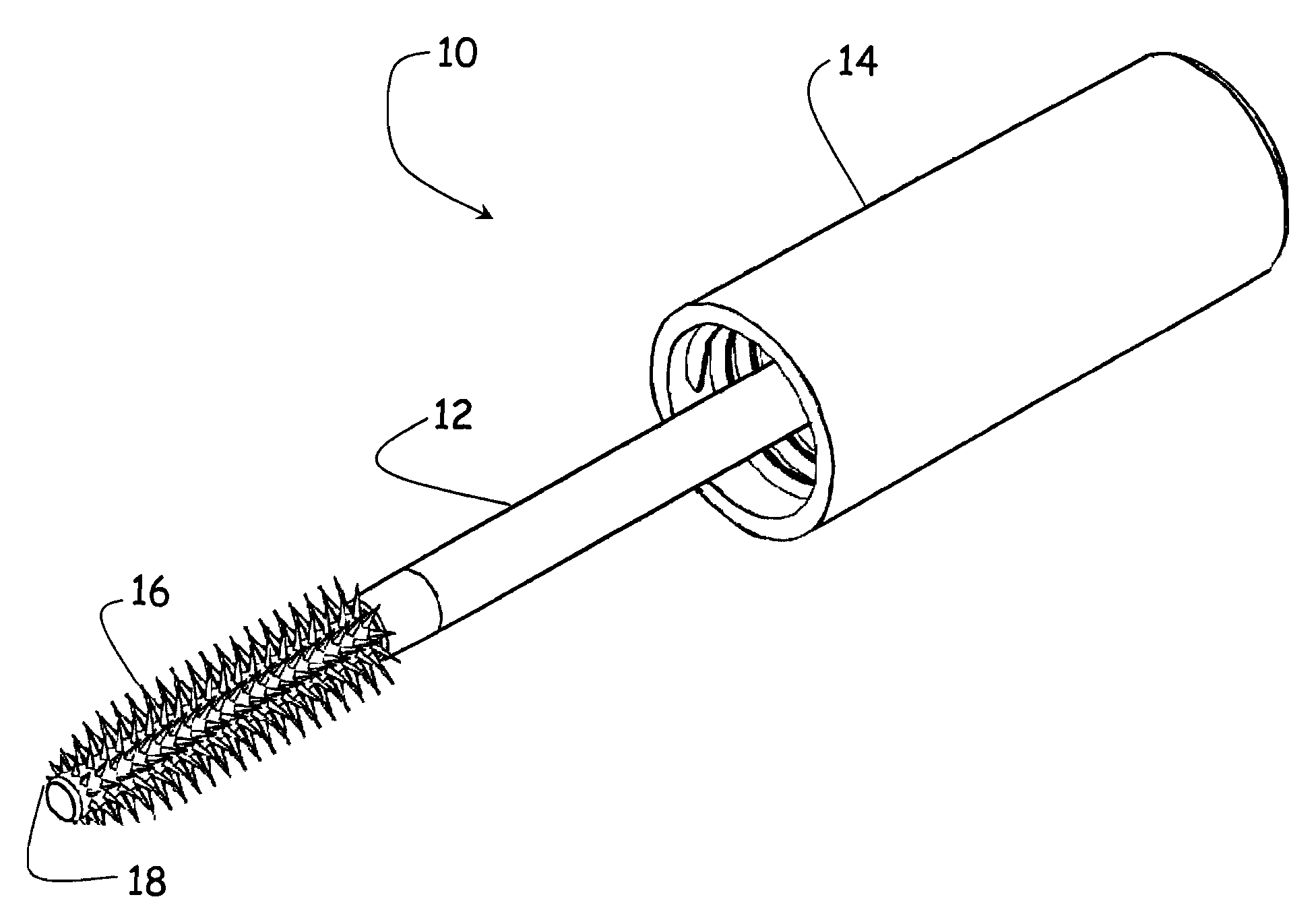
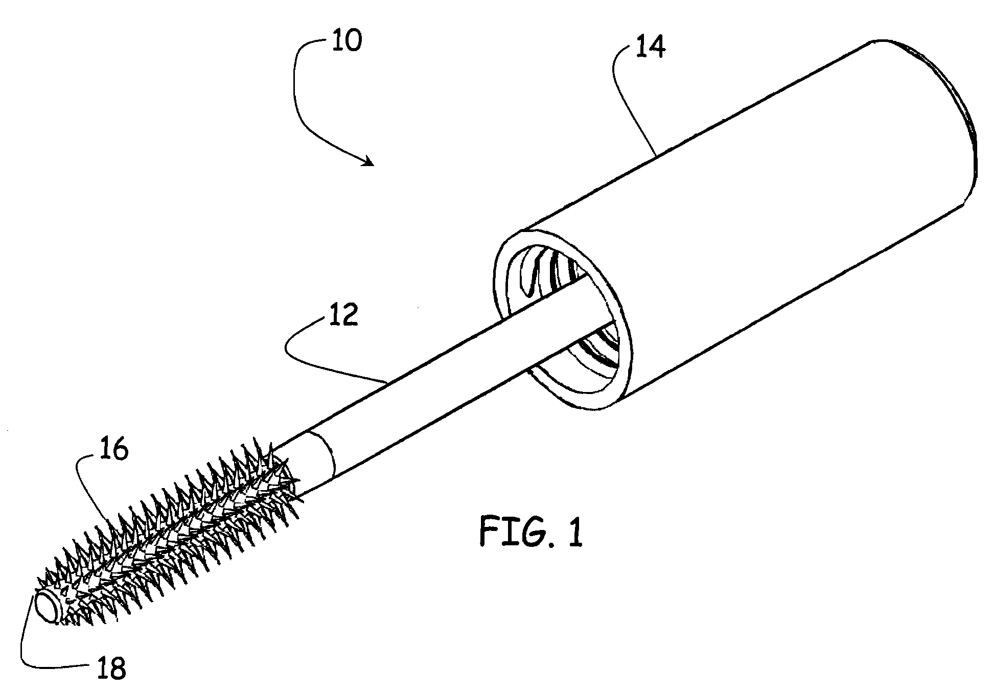
[0043]As is the case with many inventions, the present invention for a brush assembly is subject to a wide variety of embodiments. However, to ensure that one skilled in the art will be able to understand and, in appropriate cases, practice the present invention, certain preferred embodiments of the broader invention revealed herein are described below and shown in the accompanying drawing figures. Before any particular embodiment of the invention is explained in detail, it must be made clear that the following details of construction and illustrations of inventive concepts are mere examples of the many possible manifestations of the invention. It will be further appreciated that, while the present discussion relates primarily to devices for enabling the retention and application of mascara and other makeup products, the assembly disclosed herein is not so limited and may be readily applied to other industries beyond the field of cosmetics.

[0044]Turning more particularly to the draw...


PUM

PropertyMeasurementUnit
dimensionaaaaaaaaaa
lengthaaaaaaaaaa
inner diameteraaaaaaaaaa

Abstract

A brush assembly with an applicator rod, a brush sleeve with a tubular core member and a plurality of bristles, a rod hole in the distal end of the applicator rod, and a rivet for being received into the rod hole to retain the brush sleeve. A peripheral retaining wall can retain and protect a proximal end of the brush sleeve. The brush sleeve can have radially projecting, diamond-shaped bristles and can be slidably received over a body portion of the rivet or over a support stem forming a distal portion of the applicator rod. The body portion of the rivet or the support stem can have a non-circular cross section or an arcuate longitudinal profile to induce the brush sleeve to have the non-circular cross section or acruate longitudinal profile. A method for producing brush assemblies can produce brush assemblies with brush sleeves of varied cross sections.

Description

PRIORITY CLAIM[0001]This application claims priority to U.S. Provisional Patent Application No. 60 / 990,054, filed Nov. 26, 2007.FIELD OF THE INVENTION[0002]The present invention relates generally to brush constructions. More particularly, disclosed and protected herein is a manufacturing technique and a brush assembly produced thereby wherein a molded brush sleeve with spaced bristles is assembled with an applicator rod and a rivet member to produce a stable and readily adaptable applicator brush capable of retaining and applying makeup product in an efficient and advantageous manner.BACKGROUND OF THE INVENTION[0003]In general, mascara brushes have remained fundamentally similar to the twisted wire arrangements disclosed at least as early as 1964 in, for example, U.S. Pat. No. 3,214,782. In a typical twisted wire arrangement, a plurality of individual bristles are retained between metal wires that are twisted together to form a helical core. The bristles are clamped between the wire...

Claims


Application Information

Patent Timeline
Patent Type & Authority Patents(United States)
IPC IPC(8): A45D40/26
CPCA45D40/265A46B9/021Y10T29/49826A46B2200/106
Inventor HOLLOWAY, THOMAS F.DOBBINS, FREDERICK J.DUDIENSKI, STEPHEN G.LEGASSIE, RAYMOND P.
Owner HCP PACKAGING USA
Why Eureka
Try Eureka