Pneumatic tire

a pneumatic tire and tyre technology, applied in the field of pneumatic tires, can solve the problems of difficult manufacture of pneumatic tires with local variation of curvature radius of carcass lines, and achieve the effect of reducing strain and advantageously preventing groove cracking

Active Publication Date: 2012-04-03
THE YOKOHAMA RUBBER CO LTD
View PDF14 Cites 1 Cited by
  • Summary
  • Abstract
  • Description
  • Claims
  • Application Information

AI Technical Summary

Benefits of technology

[0027]According to the pneumatic tire of the present invention, because the shape of the carcass layer (carcass line) is optimized, the change of the shape of the main groove (particularly, the main groove positioned on the outer side in the width direction) is reduced between a state of the tire as it is and a state in which the tire is inflated. This reduces a strain occurring in the groove bottom of the main groove, thereby advantageously preventing a groove cracking.

Problems solved by technology

However, it is difficult to manufacture a pneumatic tire with a local variation of a curvature radius of a carcass line.Patent document 1: Japanese Patent Application Laid-open No.

Method used


Image

  • Pneumatic tire
  • Pneumatic tire
  • Pneumatic tire

Examples


first embodiment

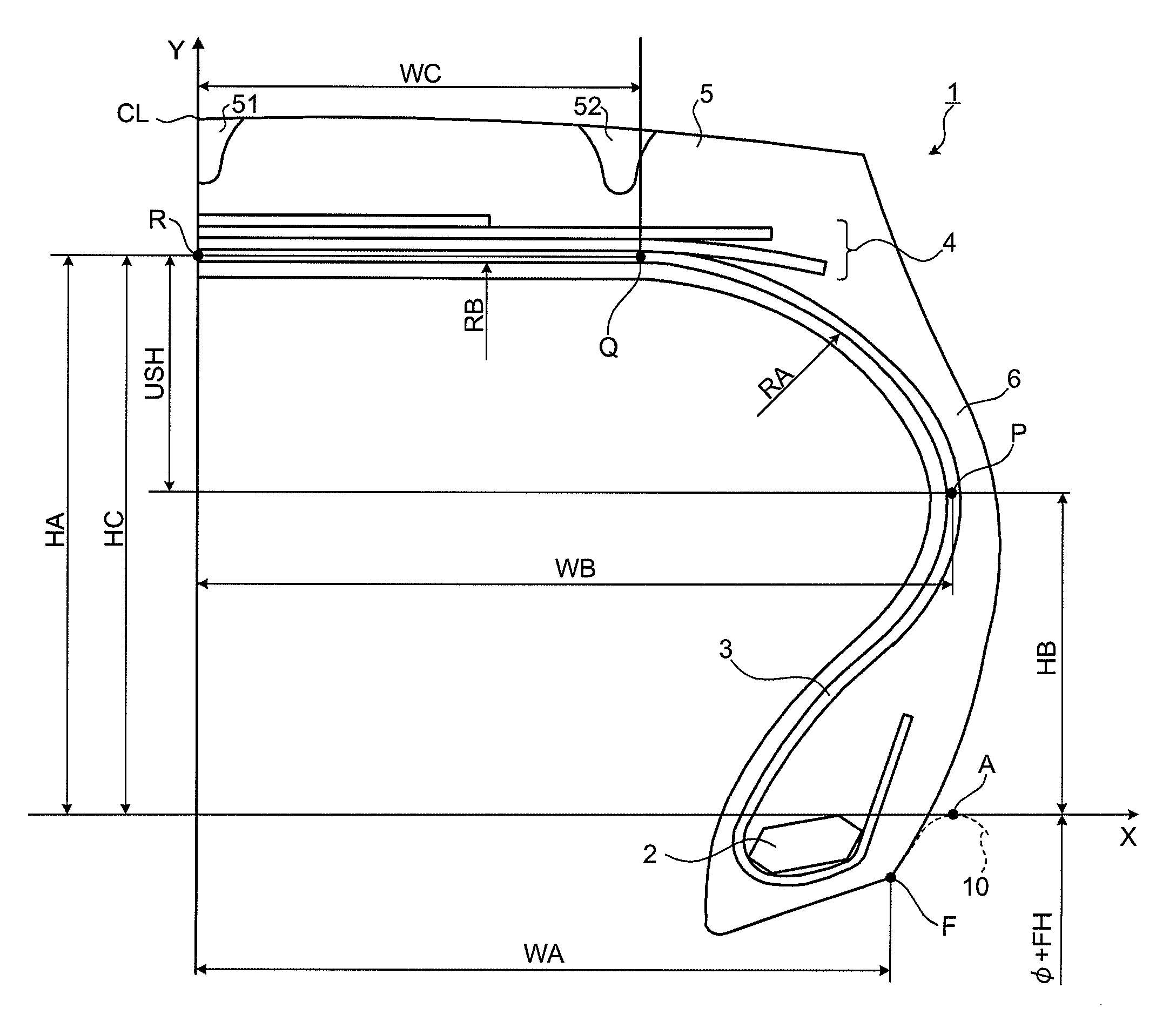
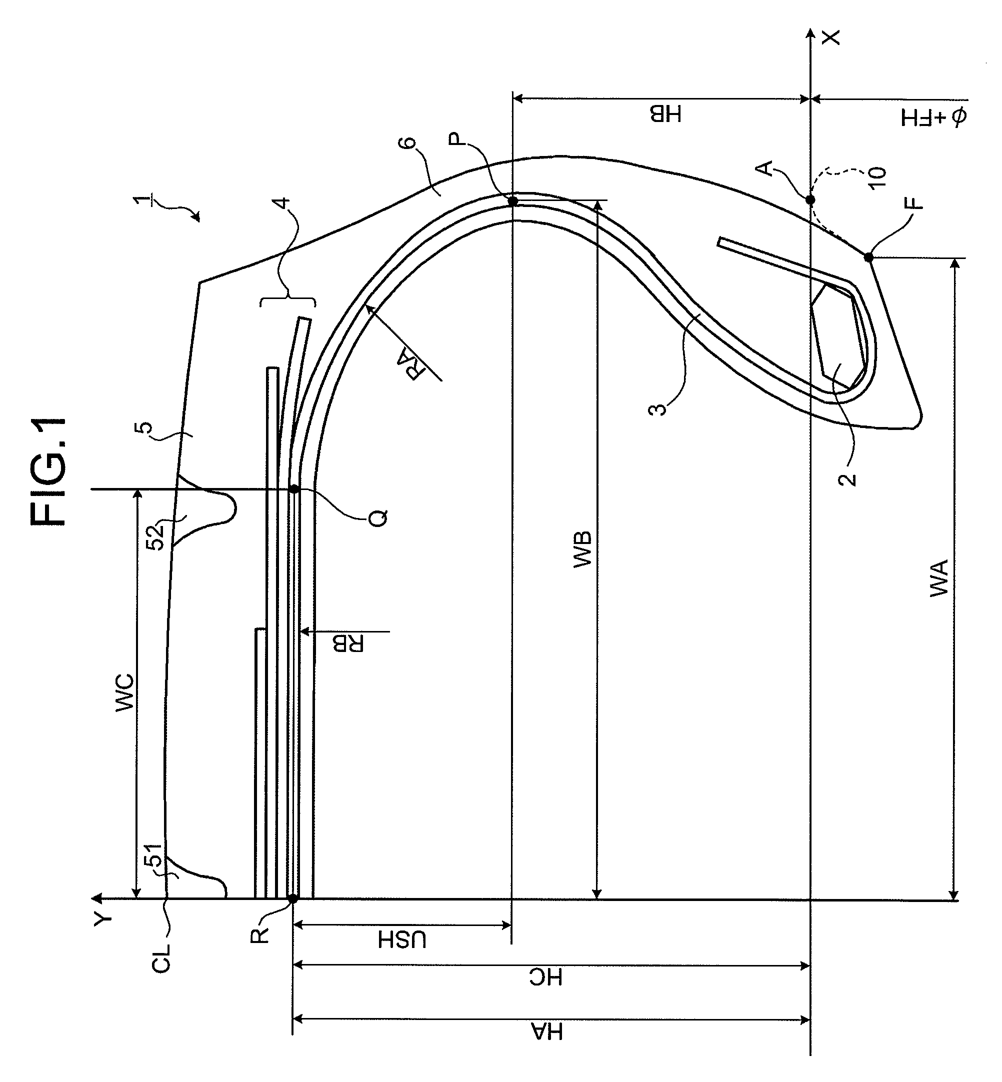
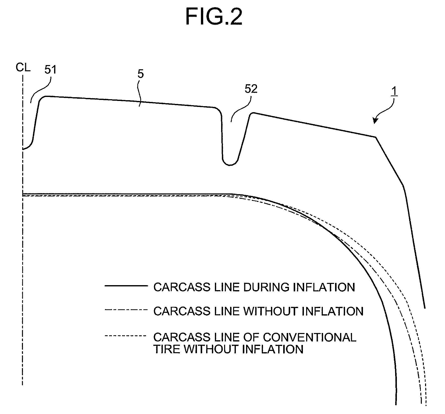
[0047]FIG. 1 is a cross section of a pneumatic tire in a tire meridian direction according to a first embodiment of the present invention. FIG. 2 is a schematic diagram for explaining a movement of the pneumatic tire shown in FIG. 1. FIGS. 3 and 4 are graphs of differences in the pneumatic tire shown in FIG. 1 depending on each tire profile. FIGS. 5 and 6 are tables of results of performance tests on pneumatic tires according to the first embodiment of the present invention.

[0048][Pneumatic Tire]

[0049]A pneumatic tire 1 includes a bead core 2, a carcass layer 3, a belt layer 4, a tread rubber 5, and a sidewall rubber 6 (see FIG. 1). The bead cores 2, each of which has an annular structure, on the left and right are constituted in a pair. The carcass layer 3 stretches across the bead cores 2 on the left and right in a toroidal shape, constituting a framework of the tire. The belt layer 4 has a plurality of belt members superposed and is arranged to a circumference of the carcass laye...

second embodiment

[0071]FIG. 7 is a graph of differences in a pneumatic tire according to a second embodiment of the present invention depending on each tire profile. FIG. 8 is a schematic diagram for explaining a carcass line of the pneumatic tire according to the second embodiment of the present invention. FIG. 9 is a table for explaining characteristics of the pneumatic tire according to the second embodiment of the present invention. FIGS. 10 and 11 are tables of results of performance tests on the pneumatic tire according to the second embodiment of the present invention.

[0072]The pneumatic tire 1 according to the second embodiment is different from the pneumatic tire 1 according to the first embodiment in that predetermined dimensional ratios USH / HA, WB / HA, and WC / WB of a cross sectional shape of the carcass layer 3 (carcass line) in a cross section of the pneumatic tire 1 in the tire meridian direction are defined by predetermined quadratic approximation.

[0073]Specifically, a distance USH from...


PUM


Abstract

In a pneumatic tire, 48%≦HB / HA≦52%, 98%≦HC / HA≦100%, 108%≦WB / WA≦115%, and 55%≦WC / WA≦75% are satisfied, where, when a line from a position A of rim height FH in tire width direction is X-axis and a line in tire radial direction via center crown CL is Y-axis, WA is distance of a half of tire base width, WB is distance from the Y-axis to a maximum width position P of a carcass layer, WC is distance from the Y-axis to an inflection point Q of the carcass layer, HA is distance from the X-axis to a peak R of the carcass layer on the center crown CL, HB is distance from the X-axis to the maximum width position P, and HC is distance from the X-axis to the inflection point Q.

Description

[0001]This application is a U.S. National Phase under 35 U.S.C. §371, of International Application No. PCT / JP2008 / 050417, filed Jan. 16, 2008.TECHNICAL FIELD[0002]The present invention relates to a pneumatic tire, and more particularly, to a pneumatic tire with a capability of preventing a groove cracking.BACKGROUND ART[0003]In a heavy-duty pneumatic tire with a low tire profile, a groove cracking (cracking in a bottom of a groove) occurs in a circumferential main groove on its outer side in its tire width direction.[0004]As for a conventional pneumatic tire concerning the above problem, a technology disclosed in Patent document 1 is known. The conventional pneumatic tire (heavy-duty pneumatic tire) includes a carcass with end portions that are bent around a pair of bead cores, a belt that is provided on an outer circumferential side of a crown portion of the carcass, a tread that is provided to the outer circumferential side of the belt, and a plurality of circumferential grooves f...

Claims


Application Information

Patent Timeline
Patent Type & Authority Patents(United States)
IPC IPC(8): B60C3/00B60C3/04B60C9/18B60C9/28
CPCB60C3/04B60C9/28B60C9/0292Y10T152/10495Y10T152/10765B60C2200/06
Inventor MARUYAMA, HIROKATSUISOBE, SATORUKOBAYASHI, HIRONORI
Owner THE YOKOHAMA RUBBER CO LTD
Why Eureka
Try Eureka