
Sliding door opening/closing device for vehicle

a technology for sliding doors and latches, which is applied in the direction of locking applications, wing accessories, transportation and packaging, etc., can solve the problems of increasing the resistance force applied to sliding doors, unable to lock with the latch, and difficult to perform positioning, so as to reduce the force necessary, reduce the force, and the effect of sufficient opening/closing drive for

Active Publication Date: 2012-03-20
FUJI ELECTRIC CO LTD
View PDF13 Cites 19 Cited by
  • Summary
  • Abstract
  • Description
  • Claims
  • Application Information

AI Technical Summary

Benefits of technology

The present invention is a sliding door opening / closing device for a vehicle that improves operability and safety while reducing noise. The device includes a magnetic lock device and a latch lifting lock device. The magnetic lock device is designed to unlock the sliding doors by rotating a columnar permanent magnet, while the latch lifting lock device is designed to unlock the sliding doors by canceling the restraint created by the magnetic lock device. The device is simple in construction, reduces the force needed to lock and unlock the latch, and restrains the locking portions to prevent them from separating during the unlocking process. The latch lifting lock device includes a wire device and a handle device that can be easily operated for emergency situations. The device ensures that the latch is securely locked when the vehicle is in a locked state.

Problems solved by technology

In the conventional sliding door opening / closing device for a vehicle, the latch has to be lowered after the latch has been correctly positioned above the lock hole, but this positioning is not easy to perform, as described hereinbelow.
However, a problem arising in a case where the crushing amount of the door edge rubber is large when the door is closed is that a resistance force applied to the sliding door increases, the latch shifts from a position above the lock hole, and locking with the latch is impossible.
Vibration preventing parts that have soundproofing, wind-stopping, and vibration damping functions are provided to abut against the sliding door when the vehicle is travelling (that is, when the door is closed), and a problem arising when these vibration preventing parts apply a force that exceeds a supposed value when the door is closed is that a resistance force applied to the sliding door increases, the latch shifts from a position above the lock hole, and locking with the latch is impossible.
The problem arising in these cases is that the resistance force falls within the specified range and the latch is closed even when a specified obstacle is squeezed by the sliding doors, and the sliding door does not comply with a door clamping test.
Because problems arise both in the case where the resistance force applied to the door is small and in the case where the force is large, as described above, this force has to be adjusted to fall in a predetermined range.
The problem is, however, that the resistance force is not easy to adjust from both sides of the range, while correctly positioning the latch above the lock hole.
A structure can be used in which a gap is provided between the door edge rubbers at the left and right sides to facilitate the adjustment operation in order to satisfy the requirements placed on both the locking operation and the specified accuracy of door clamping detection, but with the door edge rubber of a shape protruding to the left and right, water and wind penetrate from the gap and noise is generated, thereby making it difficult to follow this approach.
Because a force exceeding a large door counterforce that is applied to the latch in addition to the spring pressure pulling the latch has to be applied when the conventional door lock device is locked, a metal noise sound is loud.
A counterforce from the door edge rubber that is compressed when the door is closed is applied to the sliding door, a large door counterforce is applied to the latch in the lock device during locking, and the latch is difficult to move.
The resultant problem is that where the handle is operated in a case of emergency in a state with such a large door counterforce, the outer wire is sometimes contracted, the inner wire is not drawn relative thereto, and emergency unlocking cannot be performed.

Method used


Image

  • Sliding door opening/closing device for vehicle
  • Sliding door opening/closing device for vehicle
  • Sliding door opening/closing device for vehicle

Examples


Embodiment Construction

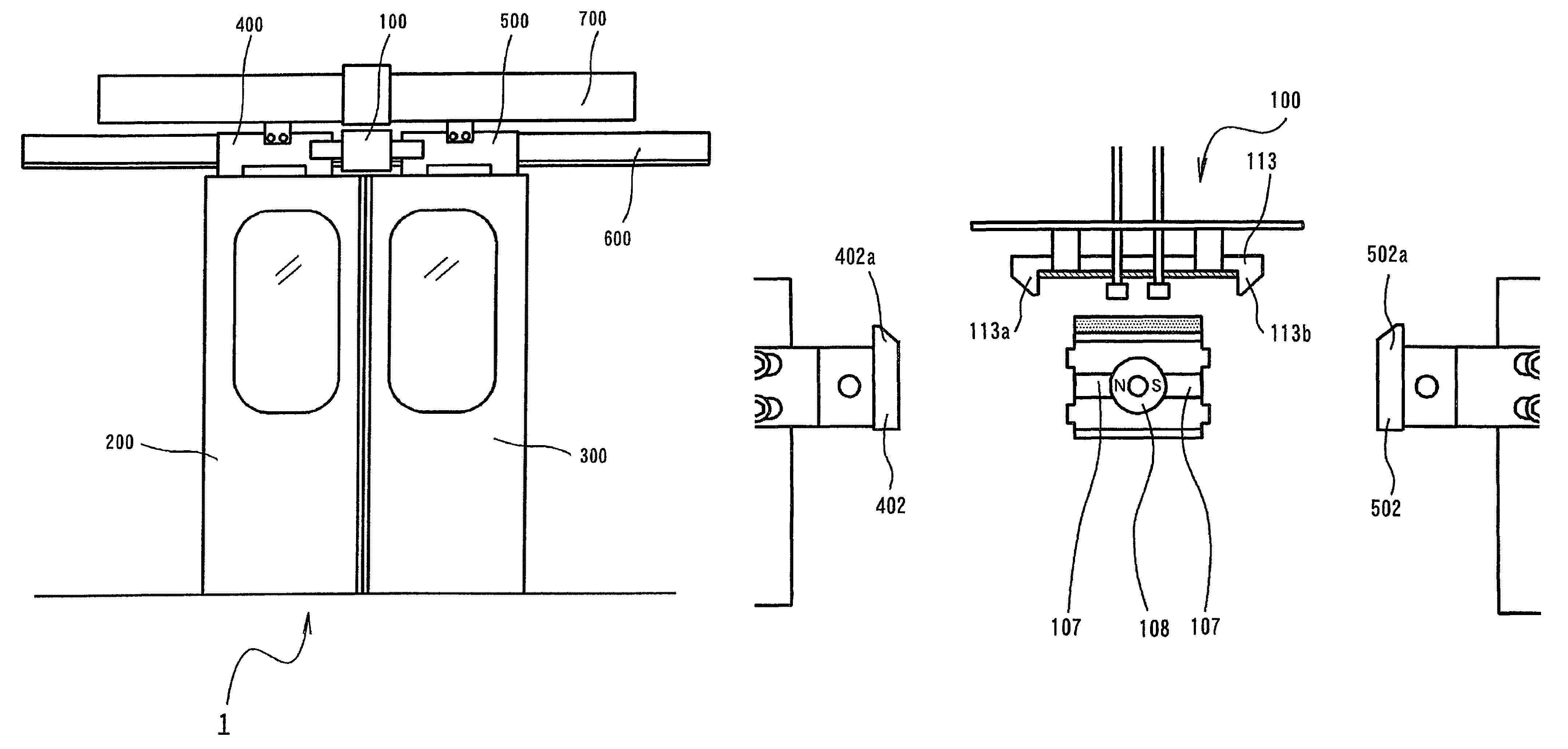
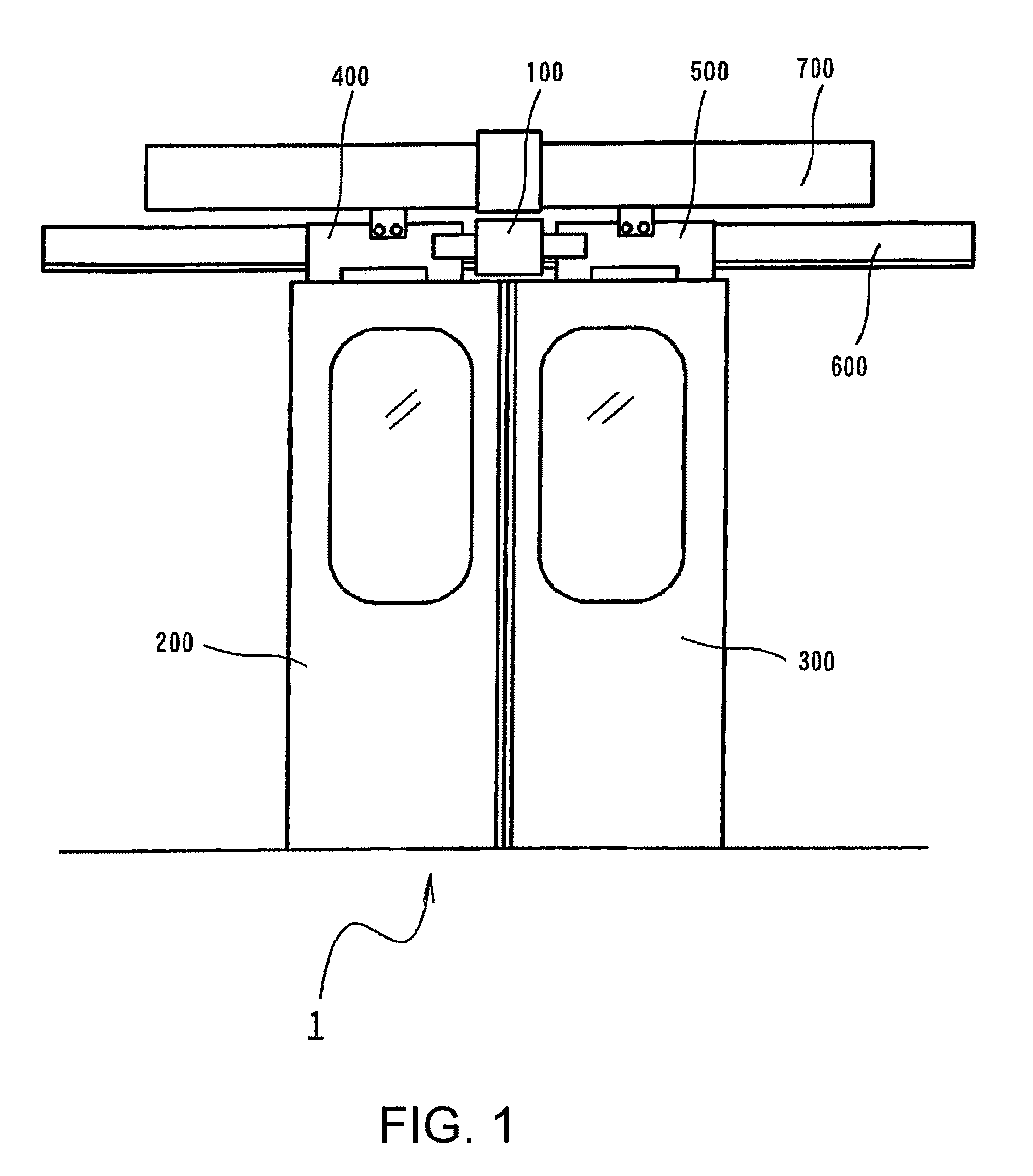
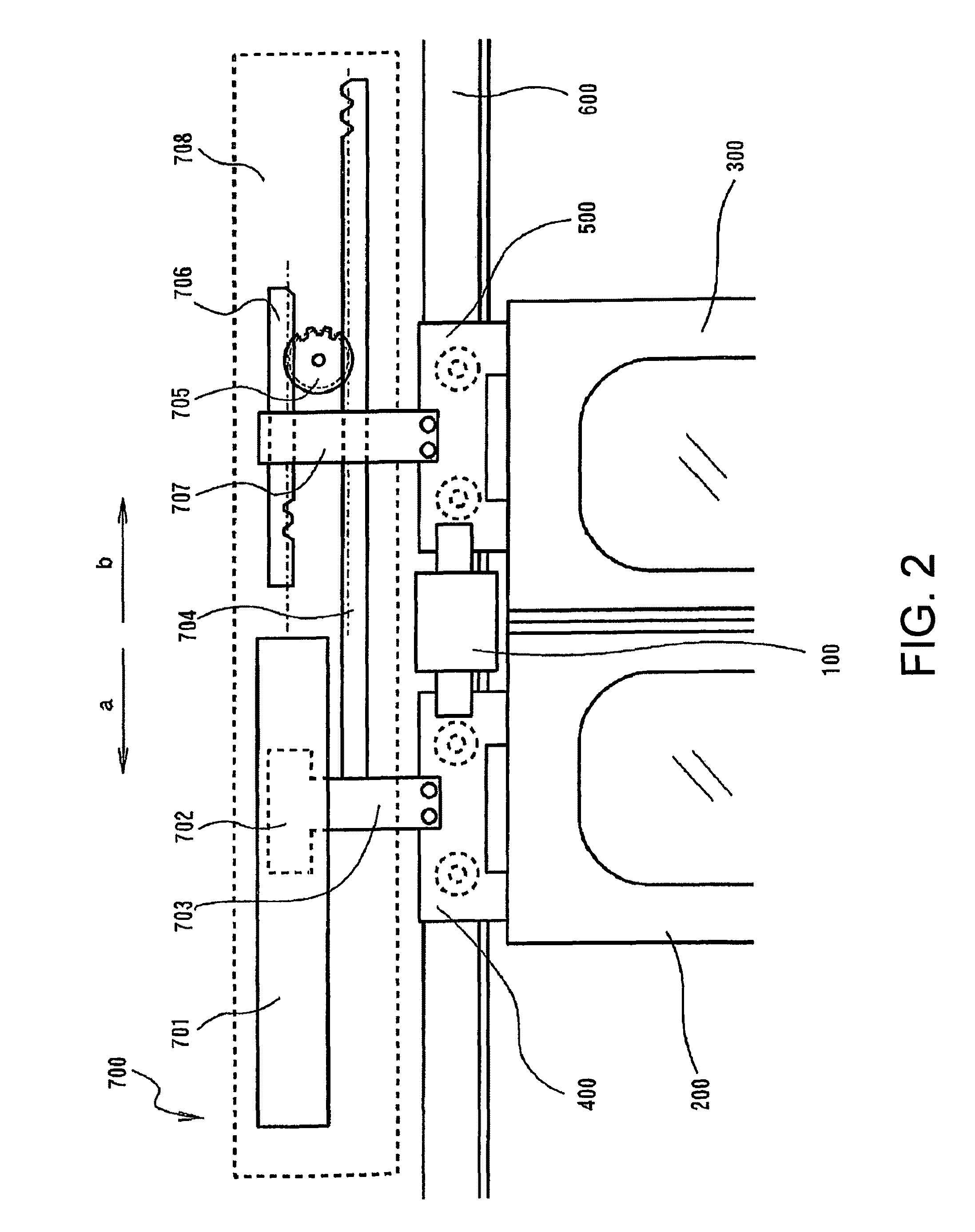
[0054]The embodiments of the present invention will be described below with reference to the appended drawings. The entire structure of the sliding door opening / closing device 1 for a vehicle will be in initially explained with reference to FIGS. 1, 2, 3, and 4. As shown in FIG. 1, the sliding door opening / closing device 1 for a vehicle is provided at least with a lock device 100, a pair of left and right sliding doors 200, 300, a rail moving bodies 400, 500, a sliding door rail 600, and an opening / closing drive device 700.

[0055]The lock device 100 has a function of locking so as to prevent the pair of left and right sliding doors 200, 300 from opening when the pair of left and right sliding doors 200, 300 have been closed. The lock device 100 is generally composed of a magnetic lock device and a latch lifting lock device that will be described below in greater detail.

[0056]The sliding doors 200, 300 open and close the entrance / exit port of a railroad train by moving in the mutually...


PUM


Abstract

The present invention provides a sliding door opening / closing device for a vehicle that applies a sufficient opening / closing drive force to the left and right sliding doors and reduces a force necessary to lock and unlock the latch, despite a simple configuration of the device, and that facilitates the manufacturing process, improves operability and safety, and reduces noise. A lock device, against both sides of which locking portions abut, rotates a columnar permanent magnet so as to form magnetic locking circuits and fixes the locking portions by magnetic forces of the locking magnetic circuits. The rotational operation of the columnar permanent magnet is converted into the downward operation of a latch, and the lowered latch restrains the locking portions with respect to the lock device.

Description

[0001]This application claim priority to Japanese Patent Application 2009-014995, filed Jan. 27, 2009, the entirety of which is incorporated herein by reference.BACKGROUND OF THE INVENTION[0002]1. Field of the Invention[0003]The present invention relates to a sliding door opening / closing device for a vehicle that serves to open and close a sliding door of a vehicle.[0004]2. Description of the Related Art[0005]The related art of sliding door opening / closing devices for vehicles is disclosed, for example, in Japanese Patent Application Laid-open No. 2000-142392 (JP-A-2000-142392), the invention being titled “Sliding Door Opening / Closing Device for Vehicle”. The sliding door opening / closing device for a vehicle disclosed in JP-A-2000-142392 is provided with a door lock device that locks and unlocks the sliding door in response to opening and closing of the sliding door. This door lock device locks the door so that it cannot be opened or closed, by dropping a latch into a lock hole. Thi...

Claims


Application Information

Patent Timeline
Patent Type & Authority Patents(United States)
IPC IPC(8): E05C7/04B61D19/00E05B47/00B61D19/02E05B63/18E05B79/20E05B81/08E05B83/02E05B83/04E05B83/36E05C19/16E05F15/60E05F15/632
CPCB61D19/005B61D19/02E05B47/026E05B65/0882E05C19/16E05C2007/007E05B83/363Y10T292/11
Inventor INAGE, AKIO
Owner FUJI ELECTRIC CO LTD
Learn More