Serial transceiver and communication method used by the serial transceiver

a transceiver and serial technology, applied in the direction of instruments, synchronisation signal speed/phase control, data switching details, etc., can solve the problems of data transceiving, data uncertainty increasing, data cost increasing,

Active Publication Date: 2012-03-13
KOREA UNIV IND & ACADEMIC CALLABORATION FOUND
View PDF2 Cites 13 Cited by
  • Summary
  • Abstract
  • Description
  • Claims
  • Application Information

AI Technical Summary

Benefits of technology

[0011]The present invention also provides a serial transceiver and a communication method used by the serial transceiver which do not transmit a reference clock while transmits data so as to solve a problem of skew between the data and the reference clock and reduce the number of transmission channels and hardware costs.
[0012]The present invention also provides a serial transceiver and a communication method used by the serial transceiver which can control a speed without an additional external operation so as not to allow data to be transmitted along with a reference clock and applies a linear phase detection method to significantly decrease jitter of a recovered clock signal.
[0013]The present invention also provides a serial transceiver and a communication method used by the serial transceiver which can recover a clock signal without an additional circuit such as a clock supplier.

Problems solved by technology

Here, the parallel transmission method has problems in that data skew which means time differences between data transmitted through difference channels may exist between the various transmission channels, and as the number of channels increases, hardware costs increase.
Since a rate of data transceived in the serial data transceiver is very high, data uncertainty increases due to noise and channel bandwidths.
However, in this method, in a case where data has to be transmitted for a long distance ranging several meters, due to skew between the data and the reference clock, the receiver may have problems in recovering data.
However, in this case, due to limitations of data edge detection, jitter of a recovered clock signal is higher than in a case of using a linear phase detector.
Therefore, speed limitations occur, and error possibility increases.
However, due to the loaded clock supplier, there are problems in that areas, costs, and power are increased.

Method used


Image

  • Serial transceiver and communication method used by the serial transceiver
  • Serial transceiver and communication method used by the serial transceiver
  • Serial transceiver and communication method used by the serial transceiver

Examples


Embodiment Construction

[0037]Exemplary embodiments of the present invention will now be described in detail with reference to the accompanying drawings.

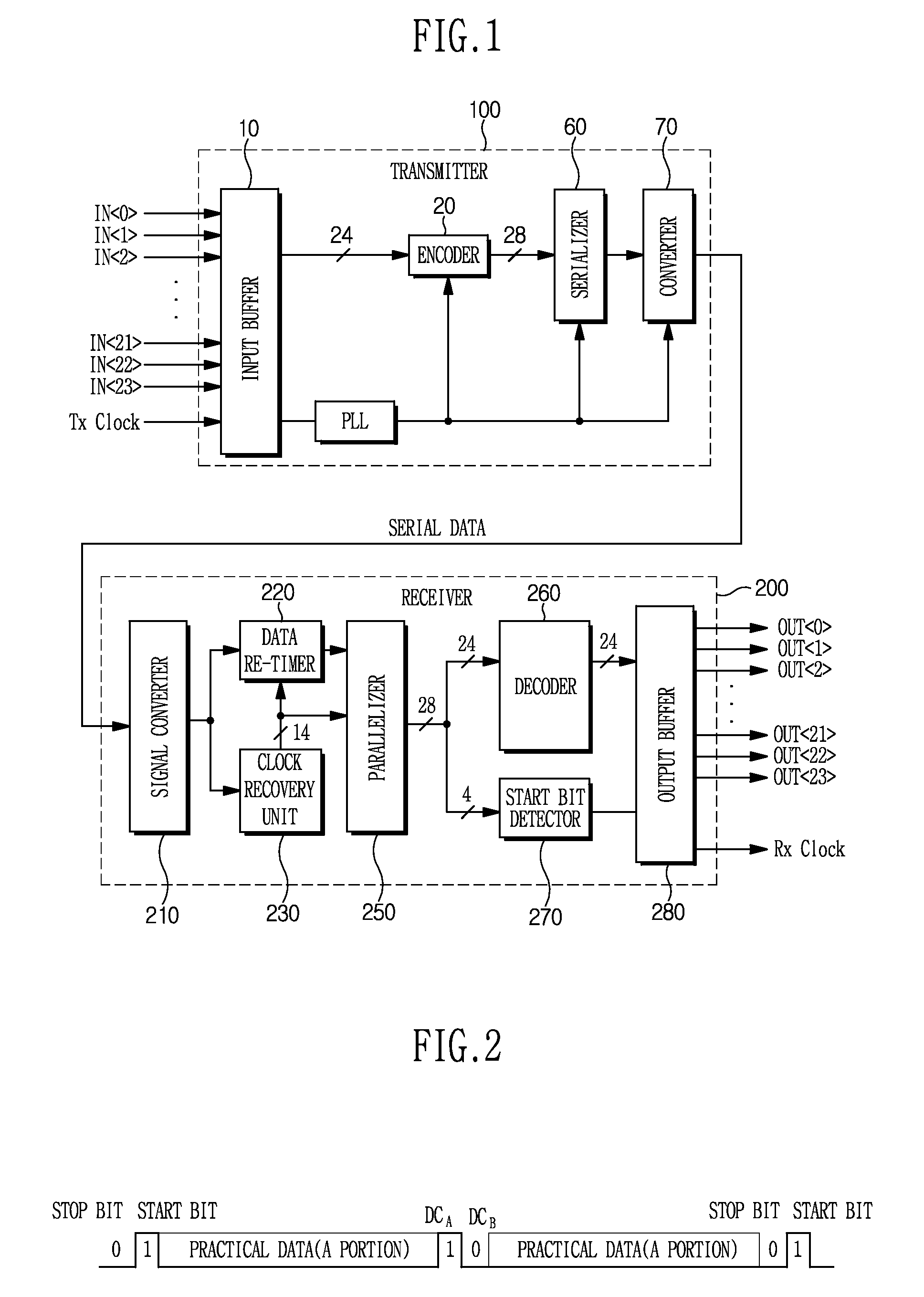
[0038]FIG. 1 is a block diagram illustrating a construction of a transceiver according to an embodiment of the present invention. The transceiver includes a transmitter 100 for receiving a parallel signal and transmitting the parallel signal as a serial signal and a receiver 200 for receiving the corresponding serial signal. According to the illustrated embodiment, the parallel data to be transmitted is 24-bit parallel data and used for a control signal interface for controlling a liquid crystal display unit.

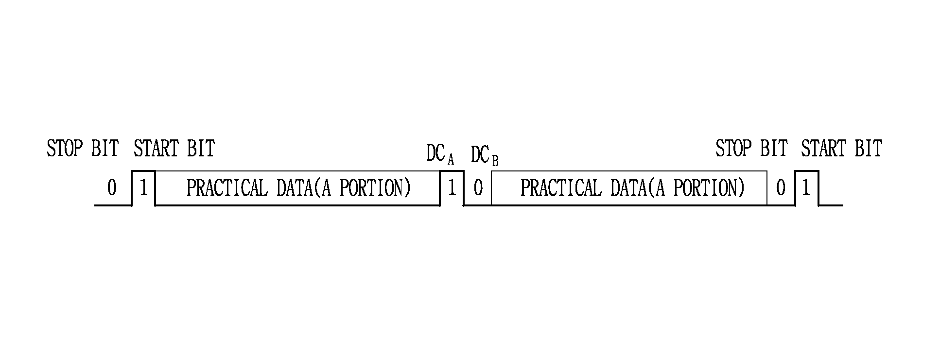
[0039]The transmitter 100 receives the 24-bit parallel data and a reference clock signal and generates parallel data to be generated as a serial signal according to a predetermined protocol through an encoder 20 of FIG. 1. According to the embodiment, the encoder 20 divides 24-bit data into two 12-bit data, inserts a 2-bit direct-current (DC) balancing...


PUM


Abstract

A high speed transceiver without using an external clock signal and a communication method used by the high speed transceiver which applies a clock recovery circuit including a coarse code generator, a frequency detector, and a linear phase detector to the receiver so as to solve problems such as skew between a reference clock and data that may occur during data transmission and jitter of a recovered clock while an embedded clock method of applying clock information to data is used.

Description

BACKGROUND OF THE INVENTION[0001]1. Field of the Invention[0002]The present invention relates to a serial transceiver, and more particularly, to a high speed transceiver without using an external clock signal and a communication method used by the high speed transceiver.[0003]2. Description of the Related Art[0004]As various communication methods have been developed and widely used, the demand of users for multimedia increases. Accordingly, studies for transmitting a larger amount of data at a higher speed more stably and minimizing a hardware configuration needed for the transmission have been made.[0005]In general, in order to increase a data rate, one is selected from among a parallel transmission method of increasing the number of channels and simultaneously transmitting a number of pieces of data and a serial transmission method of transmitting data at a high speed through a single channel, to maximize the functions. Here, the parallel transmission method has problems in that d...

Claims


Application Information

Patent Timeline
Patent Type & Authority Patents(United States)
IPC IPC(8): H03D3/24
CPCG06F13/385H03L7/0807H03L7/087H03L7/0891H03L7/095H03L7/099H03L7/10H04L7/044H04L7/033H03L7/113G06F13/14G06F13/38G06F15/16H04L12/02
Inventor KIM, CHULWOOJUNG, INHWA
Owner KOREA UNIV IND & ACADEMIC CALLABORATION FOUND
Why Eureka
Try Eureka