
Speed change control system of automatic transmission

a control system and automatic transmission technology, applied in the direction of clutches, mechanical equipment, instruments, etc., can solve the problems of not being able to accurately detect the speed and/or the gear ratio of the automatic transmission, and it is practically impossible or at least difficult to achieve accurate detection of the automatic transmission speed and/or the gear ratio. , to achieve the effect of reducing the hydraulic pressure, and reducing the shock

Active Publication Date: 2012-03-06
JATCO LTD +1
View PDF23 Cites 16 Cited by
  • Summary
  • Abstract
  • Description
  • Claims
  • Application Information

AI Technical Summary

Benefits of technology

[0008]Accordingly, an object of the present invention is to provide a speed change control system of an automatic transmission, which is free of the above-mentioned drawbacks.
[0009]That is, in accordance with the present invention, there is provided a speed change control system of an automatic transmission, which establishes both suppression of the shock and reduction of the speed change time of the transmission at the time when a speed change of the transmission is carried out under a very low speed running of the vehicle.
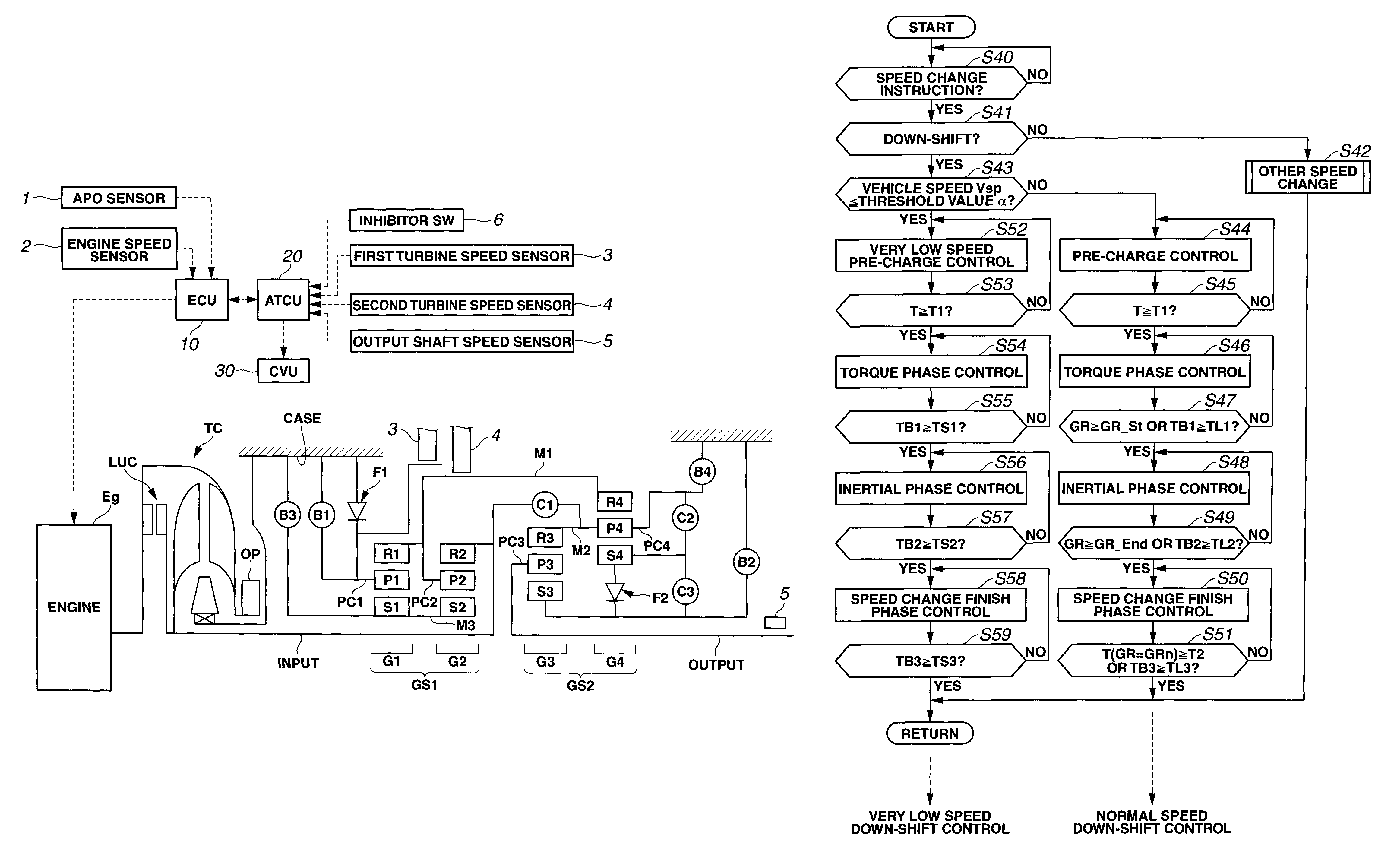
[0010]In accordance with a first aspect of the present invention, there is provided a speed change control system of an automatic transmission mounted on a motor vehicle, the transmission having a first frictional element that changes its operation condition from a disengaged condition to an engaged condition upon issuance of a speed change instruction, a second frictional element that changes its operation condition from an engaged condition to a disengaged condition upon issuance of the speed change instruction, a vehicle speed sensor that detects a speed of the vehicle and a control device that controls a hydraulic pressure applied to the first frictional element based on information on a target gear ratio, the speed change control system comprising a judge section that judges whether or not the vehicle speed detected by the vehicle speed sensor is equal to or lower than a predetermined very low value; a very low vehicle speed pre-charge control section that, when, upon issuance of the speed change instruction, the judge section judges that the vehicle speed detected by the vehicle speed sensor is equal to or lower than the predetermined very low value, sharply increases the hydraulic pressure applied to the first frictional element, sharply reduces the hydraulic pressure and then holds the hydraulic pressure higher than a given value capable of effecting a piston stroke of a corresponding piston unit for the first friction element until a time when the piston stroke is completed; and a very low vehicle speed phase control section that, upon completion of the piston stroke, increases the hydraulic pressure to a maximum level in a time that is shorter than that set when the vehicle speed detected by the vehicle speed sensor is higher than the predetermined very low value.

Problems solved by technology

As is known, when a motor vehicle runs at a very low speed, it is practically impossible or at least difficult to accurately detect the vehicle speed and / or the gear ratio of the automatic transmission, which are needed for appropriately controlling operation of the automatic transmission.

Method used


Image

  • Speed change control system of automatic transmission
  • Speed change control system of automatic transmission
  • Speed change control system of automatic transmission

Examples


Embodiment Construction

[0019]In the following, a speed change control system of an automatic transmission according to the present invention will be described in detail with reference to the accompanying drawings.

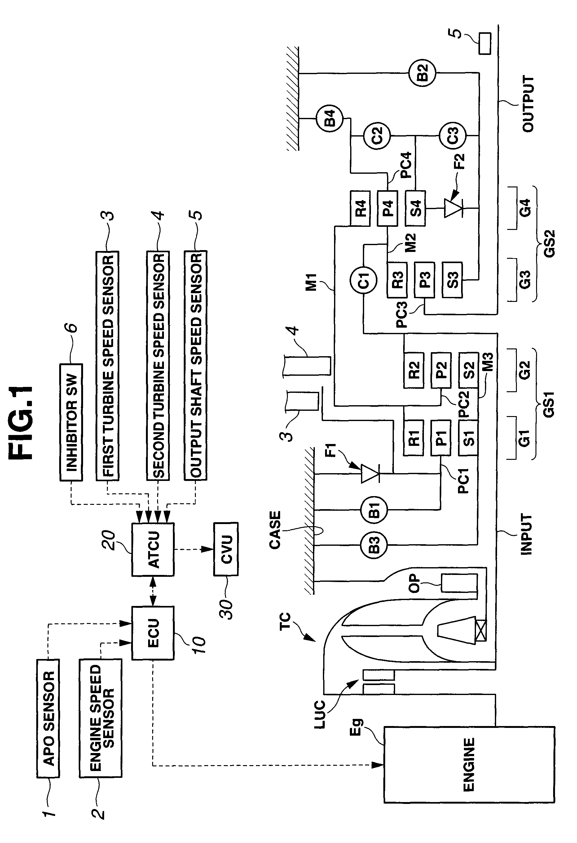
[0020]Referring to FIG. 1, there is schematically shown an automatic transmission to which the speed change control system of the present invention is practically applied.

[0021]The automatic transmission shown in FIG. 1 is of a type having seven forward speeds and one reverse speed.

[0022]As shown in the drawing, a drive force produced by an engine “Eg” is inputted to an input shaft “Input” through a torque converter “TC”. The input drive force is treated by four planetary gear units “G1, G2, G3 and G4” and seven frictional elements “C1, C2, C3, B1, B2, B3 and B4” to be subjected to a rotation speed change and transmitted to an output shaft “Output”.

[0023]An oil pump “OP” is coaxially mounted on a pump impeller of the torque converter “TC”, so that the oil pump “OP” compresses a hydraulic liquid (...


PUM


Abstract

When it is judged that a vehicle speed detected by a vehicle speed sensor is equal to or lower than a predetermined very low value, that is, for example, 5 km / h, the hydraulic pressure applied to an engaging-side frictional element is sharply increased, sharply reduced and then held higher than a given value capable of effecting a piston stroke of a corresponding piston unit until a time when the piston stroke is completed. Upon completion of the piston stroke, the hydraulic pressure is increased to a maximum value in a time that is smaller or shorter than that set when the detected vehicle speed is higher than the predetermined very low value.

Description

BACKGROUND OF THE INVENTION[0001]1. Field of the Invention[0002]The present invention relates to speed change control systems of an automatic transmission, and more particularly to the speed change control systems of a type that allows the transmission to exhibit a higher speed change response (viz., a rapid operation response to a speed change instruction) when the vehicle is running at a very slow speed inducing a difficulty in accurately detecting the vehicle speed.[0003]2. Description of the Related Art[0004]As is known, when a motor vehicle runs at a very low speed, it is practically impossible or at least difficult to accurately detect the vehicle speed and / or the gear ratio of the automatic transmission, which are needed for appropriately controlling operation of the automatic transmission.[0005]In order to compensate a delayed response of speed change inevitably exhibited by an automatic transmission at the time when the motor vehicle runs at such very slow speed, Japanese L...

Claims


Application Information

Patent Timeline
Patent Type & Authority Patents(United States)
IPC IPC(8): F16H59/20F16D48/12G06F19/00F16H59/44F16H59/46F16H61/06F16H61/68F16H61/684F16H61/686
CPCF16H61/061F16H59/44Y10T477/675
Inventor SUZUKI, MASAMIENDO, GOH
Owner JATCO LTD
Learn More