
Portable turbine systems

a technology of portable turbines and turbines, applied in the field of portable turbines, can solve the problems of large turbines that require zoning and permits, face numerous challenges, and environmental impact, and achieve the effect of convenient transportation and low cos

Inactive Publication Date: 2012-03-06
TONG LUCAS +1
View PDF14 Cites 10 Cited by
  • Summary
  • Abstract
  • Description
  • Claims
  • Application Information

AI Technical Summary

Benefits of technology

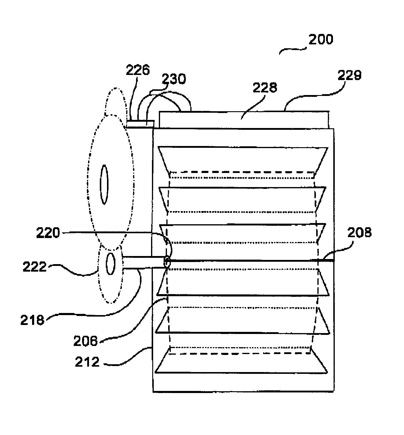
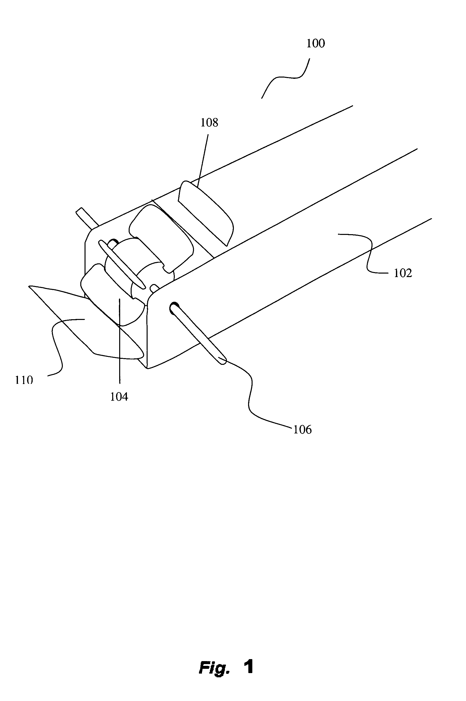
[0008]In one embodiment, the present invention provides an inexpensive and portable turbine system that is easily transportable. The turbine system can generate electricity for different purposes, such as to charge a battery, a computer and a cellular phone, and to run other electrical devices. With the systems being portable, a user can take it around and have power even when the user is stranded in a remote and isolated area. For example, if there is a running stream nearby, a portable stream turbine system, according to one embodiment, can provide electricity for the user.
[0017]In one approach, a portable stream turbine system or an array of stream turbine systems can be prevented from being drifted away by different drifting prevention mechanisms. The drifting prevention mechanisms prevent the system(s) from being drifted away when the system(s) is in a fluid. The drifting prevention mechanisms can also substantially maintain the orientation of the system(s), which enhances the liquid flow into the input channel(s) of the system(s).

Problems solved by technology

These projects are on the right track, but face numerous challenges.
For example, they are very expensive.
In addition, such large projects with huge turbines require zoning and permits, and have their environmental impact.
In view of large fluctuation in oil prices and the possibility of global recession, realizing these large and expensive projects may be very difficult.

Method used


Image

  • Portable turbine systems
  • Portable turbine systems
  • Portable turbine systems

Examples


Embodiment Construction

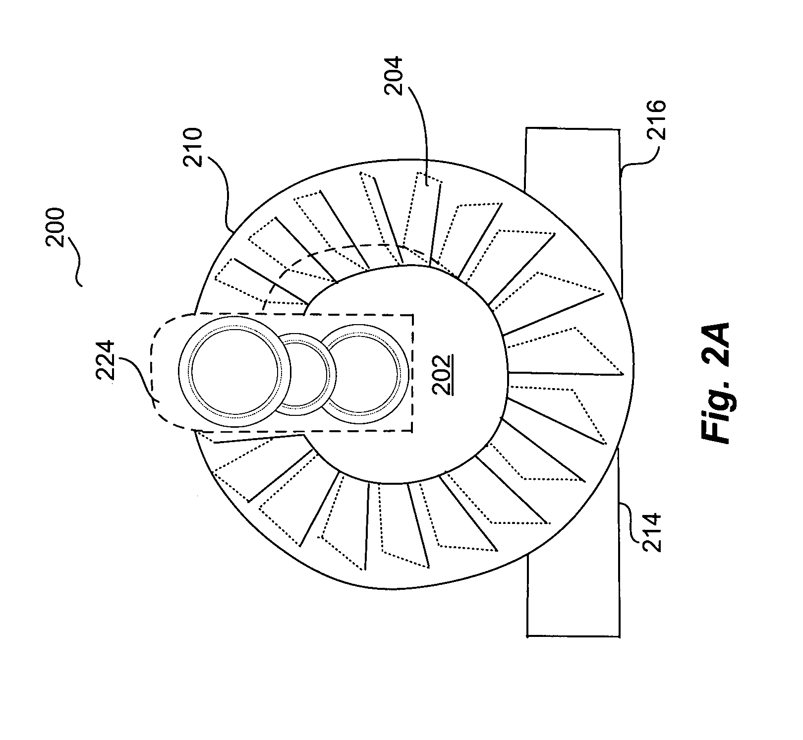
[0027]A number of embodiments of the invention pertain to a portable turbine system. The system can be portable or handheld. The turbine system transforms kinetic energy in a fluid into kinetic energy in a turning turbine, which, in turn, generates electricity via a generator. The electricity generated can be used for different purposes. To illustrate, electricity generated can be stored in an energy storage medium, such as a battery. Or the electricity can be used to charge a computer, a cellular phone etc. Instead of storing the electricity, the electricity can be used to generate light, run an electronic device or operate other appliances.

[0028]In one embodiment, a portable turbine system includes a portable or handheld hollow tube, with a turbine embedded inside the tube. Fluid flowing through the tube turns the turbine to generate electricity. Examples for the fluid include some form of gases, such as air, or some form of liquid, such as water, which can be from a stream, rain,...


PUM


Abstract

Novel apparatus and techniques for harnessing wind and / or moving-liquid energy using one or more portable turbine systems are disclosed. One embodiment includes a portable stream turbine system having a hub with many paddles, held by an axle in a housing. The system further includes a disk fixed to the hub and extended out of the housing to be also fixed to a gear structure, which is connected to a generator. The output of the generator can be connected to electronics to perform different functions. Another embodiment includes a number of portable turbine systems removably attached together to form an array. In one example, the number of portable turbine systems in an array can be adjustable, depending on needs. The different embodiments regarding a stream turbine system can further include a floatation mechanism to keep the different embodiments afloat or partially afloat in a fluid. The different embodiments regarding a stream turbine system or an array of stream turbine systems can also include a drifting prevention mechanism to prevent the embodiments from being drifted away, and to substantially maintain the orientation of the embodiments in a fluid.

Description

CROSS REFERENCE TO RELATED APPLICATIONS[0001]This application claims benefit of (i) U.S. Provisional Patent Application No. 61 / 005,180, filed Dec. 2, 2007, and entitled “Turbines in Household Drainage Pipes and Portable Turbine Systems,” and (ii) U.S. Provisional Patent Application No. 61 / 065,541, filed Feb. 12, 2008, and entitled “Turbines in Household Drainage Pipes and Portable Turbine Systems,” and (iii) U.S. Provisional Patent Application No. 61 / 126,166, filed Apr. 30, 2008, and entitled “Portable Turbine Systems,” all of which are hereby incorporated herein by reference.BACKGROUND OF THE INVENTION[0002]1. Field of the Invention[0003]The present invention relates generally to turbines and more particularly to portable turbines.[0004]2. Description of the Related Art[0005]Energy from wind and flowing liquid are renewable and clean natural resources. They do not pollute the environment, and could provide tremendous amount of the energies we need. Thus, it is not surprising that n...

Claims


Application Information

Patent Timeline
Patent Type & Authority Patents(United States)
IPC IPC(8): F03B13/00
CPCF03B17/063F05B2240/93Y02E10/20
Inventor TONG, LUCASSMITH, CAMERON
Owner TONG LUCAS
Learn More