
Hydrogenation process for fluorocarbons

a technology of fluorocarbons and hydrocarbons, which is applied in the field of fluorinated olefins, can solve the problems of reduced yield of desired products, inconvenient recycling of reaction products, and disadvantages of the type described above, and achieves improved yield, improved surface area, and reduced pressure drop

Active Publication Date: 2012-03-06
HONEYWELL INT INC
View PDF19 Cites 0 Cited by
  • Summary
  • Abstract
  • Description
  • Claims
  • Application Information

AI Technical Summary

Benefits of technology

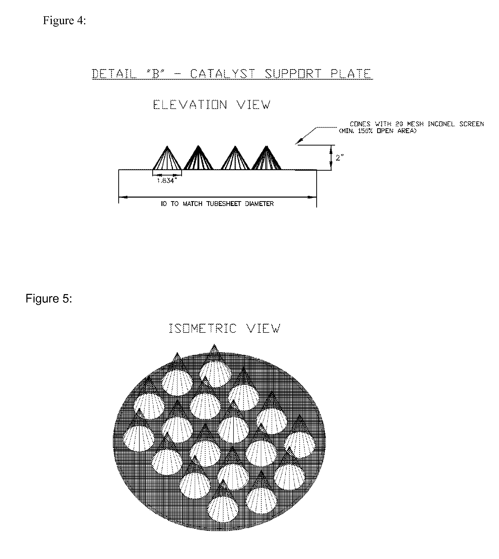
The present invention is about a process for the catalytic hydrogenation of fluoro-olefins to fluorocarbons using a multi-tube shell and tube reactor. The invention provides better temperature control, lower capital investment, higher product yields, and a higher on-stream factor compared to traditional methods. The invention uses a conical or cone-shaped catalyst support member which increases the surface area and reduces the buildup of fine material. The conical design also allows for longer operating time due to higher surface area availability to pass fines. Overall, the invention provides a better and more efficient process for the hydrogenation of fluoro-olefins.

Problems solved by technology

Applicants have discovered that the processes of the type described above have disadvantages and / or are not as effective and / or economical as would be practically necessary for large scale commercial production.
If the heat generated from the reaction is not adequately managed, the high temperatures in the reactor may cause excess hydrogenation, or other side product formation, resulting in reduced yields of the desired product.
Recycle of reaction product may not always be suitable especially when the reaction product is susceptible to hydrogenation.
Similarly, when the latent heat of the reaction product is low, as in fluorocarbons, processing requires large amounts of recycling, thus making the process less economical.

Method used


Image

  • Hydrogenation process for fluorocarbons
  • Hydrogenation process for fluorocarbons
  • Hydrogenation process for fluorocarbons

Examples


Embodiment Construction

[0045]Referring to the drawings accompanying this disclosure, preferred embodiments of the invention are illustrated as follows:

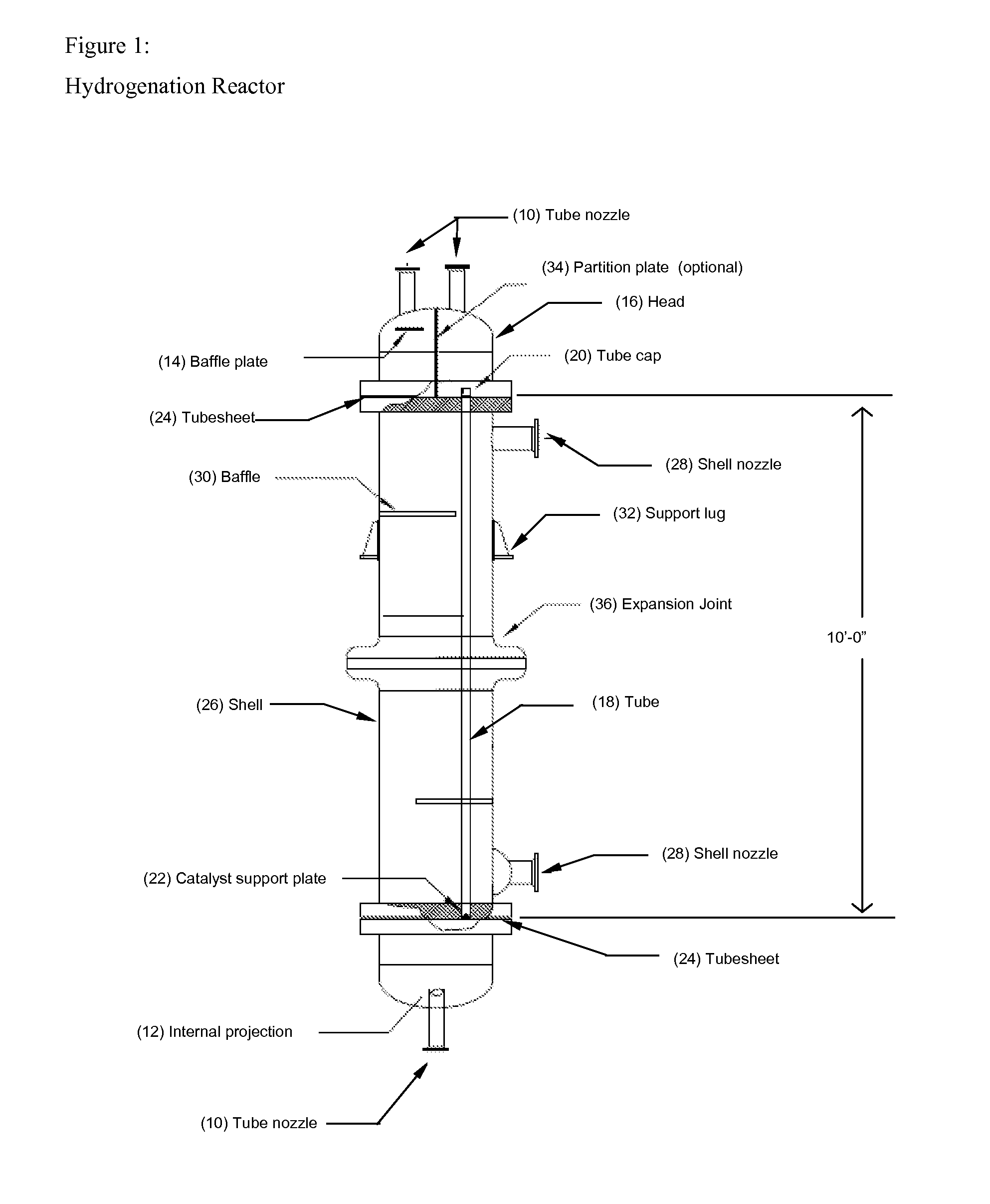
[0046]FIG. 1 shows one embodiment of a tube and shell reactor useful in the process of the present invention. As shown therein, the following component parts are employed:[0047]10—Tube nozzle[0048]12—Internal projection[0049]14—Baffle Plate[0050]16—Head[0051]18—Tube[0052]20—Tube cap[0053]22—Catalyst support plate[0054]24—Tubesheet[0055]26—Shell[0056]28—Shell nozzle[0057]30—Baffle[0058]32—Support lug[0059]34—Partition plate[0060]36—Expansion joint

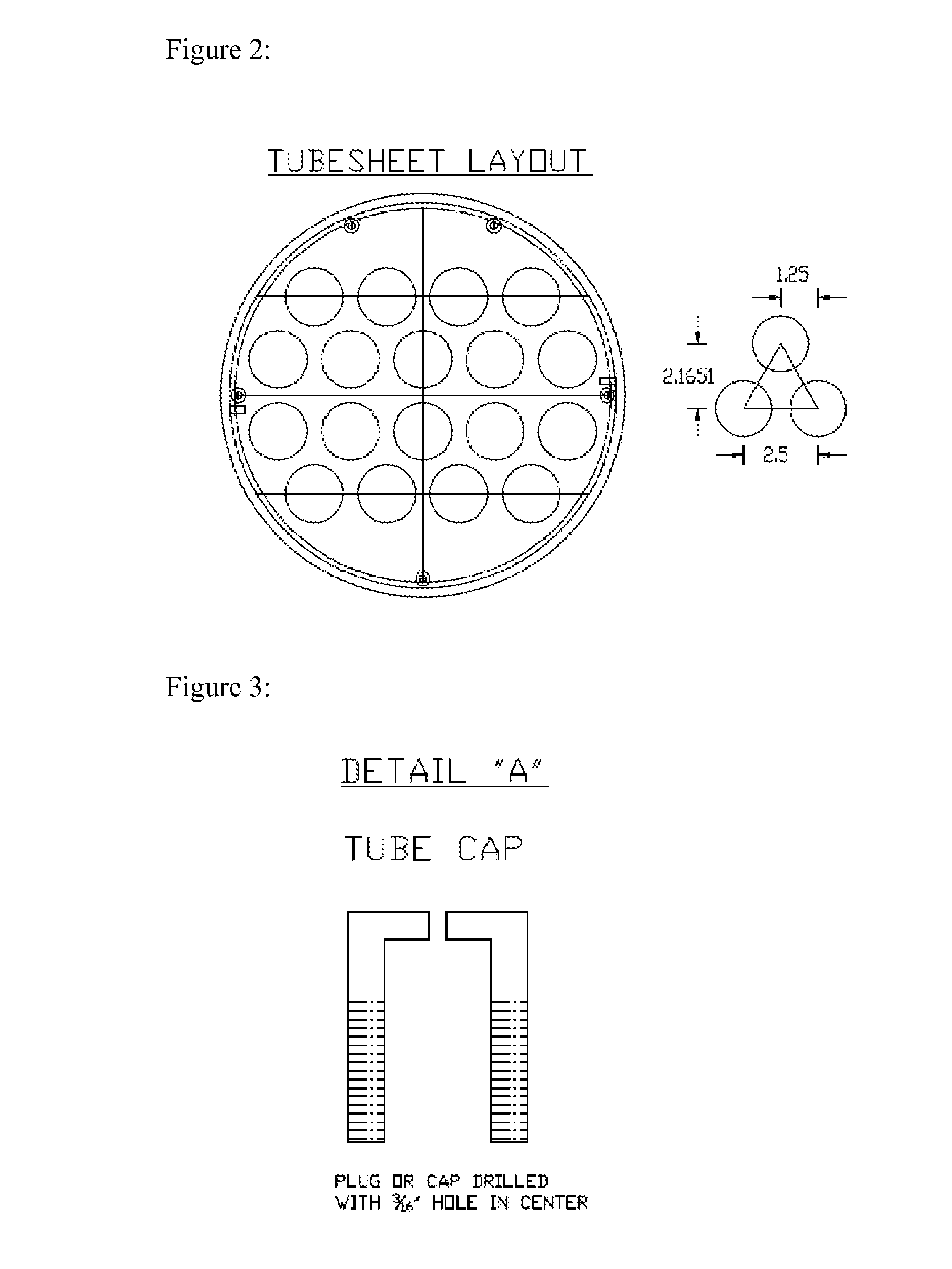
[0061]FIG. 2 illustrates a preferred embodiment of the tubesheet layout for the reactor shown in FIG. 1.

[0062]The bottom tubesheet should be ground down to a smooth finish. This will allow for a good seal between the tubes (18) holding the catalyst and the catalyst support plate (22).

[0063]FIG. 3 illustrates one preferred embodiment of tube caps used in the reactor shown in FIG. 1. The tube caps aid in the proper di...


PUM

PropertyMeasurementUnit
diameteraaaaaaaaaa
heightaaaaaaaaaa
diameteraaaaaaaaaa

Abstract

Disclosed is a process and apparatus for the catalytic hydrogenation of fluoroolefins to fluorocarbons where the reaction is carried out in a multi-tube shell and tube reactor. Reactions involving hydrogenation of fluoro-olefins are typically exothermic. In commercial processes where a fluoro-olefin C(n)H(2n−x)F(x) to C(n)H(2n−x+2)F(x) is hydrogenated (e.g. hexafluoropropylene to 236ea, 1225ye to 245eb, and the like), inadequate management or control of heat removal may induce excess hydrogenation, decomposition and hot spots resulting in reduced yields and potential safety issues. In the hydrogenation of fluoro-olefins, it is therefore necessary to control the reaction temperature as precisely as practical to overcome challenges associated with heat management and safety.

Description

FIELD OF THE INVENTION[0001]Fluorocarbons, particularly fluorinated olefins, as a class, have many and varied uses, including as chemical intermediates and monomers. In particular, the hydrogenated products are useful as refrigerants, monomers or intermediates for preparing refrigerants, particularly those identified as having low global warming potential.BACKGROUND OF THE INVENTION[0002]Several methods for preparing fluorinated olefins are known. Likewise, various reactors for conducting catalytic reactions are known. The following references are cited as non-exclusive examples. These documents are hereby incorporated herein by reference:[0003]U.S. Pat. No. 4,876,405 discloses a process for preparing fluoroethylenes and chlorofluoro-ethylenes from chlorofluoroethanes.[0004]U.S. Pat. No. 5,118,888 discloses a process for the preparation of 1,2-difluoro-ethylene and 1-chloro-1,2-difluoroethylene.[0005]U.S. Pat. No. 5,396,000 discloses a process for producing CF3CHFCH2F using vapor ph...

Claims


Application Information

Patent Timeline
Patent Type & Authority Patents(United States)
IPC IPC(8): C07C17/00B01J35/00
CPCB01J8/067C07C17/354C07C19/08B01J2208/00849B01J2208/00884B01J8/06
Inventor KOPKALLI, HALUKCHIU, YUONRODRIGUES, ORLANDO GEORGECERRI, GUSTUNG, HSUEH SUNGCOTTRELL, STEPHEN A.
Owner HONEYWELL INT INC
Learn More