Pressure differential system for controlling high pressure refill gas flow into on board vehicle fuel tanks
a technology of high pressure and fuel tank, which is applied in the direction of liquid handling, container discharging methods, packaged goods types, etc., can solve the problems of prohibitive use of mass flow meters by consumers, and achieve the effects of high pressure, stable operation, and shortening refueling tim
- Summary
- Abstract
- Description
- Claims
- Application Information
AI Technical Summary
Benefits of technology
Problems solved by technology
Method used
Image
Examples
example 1
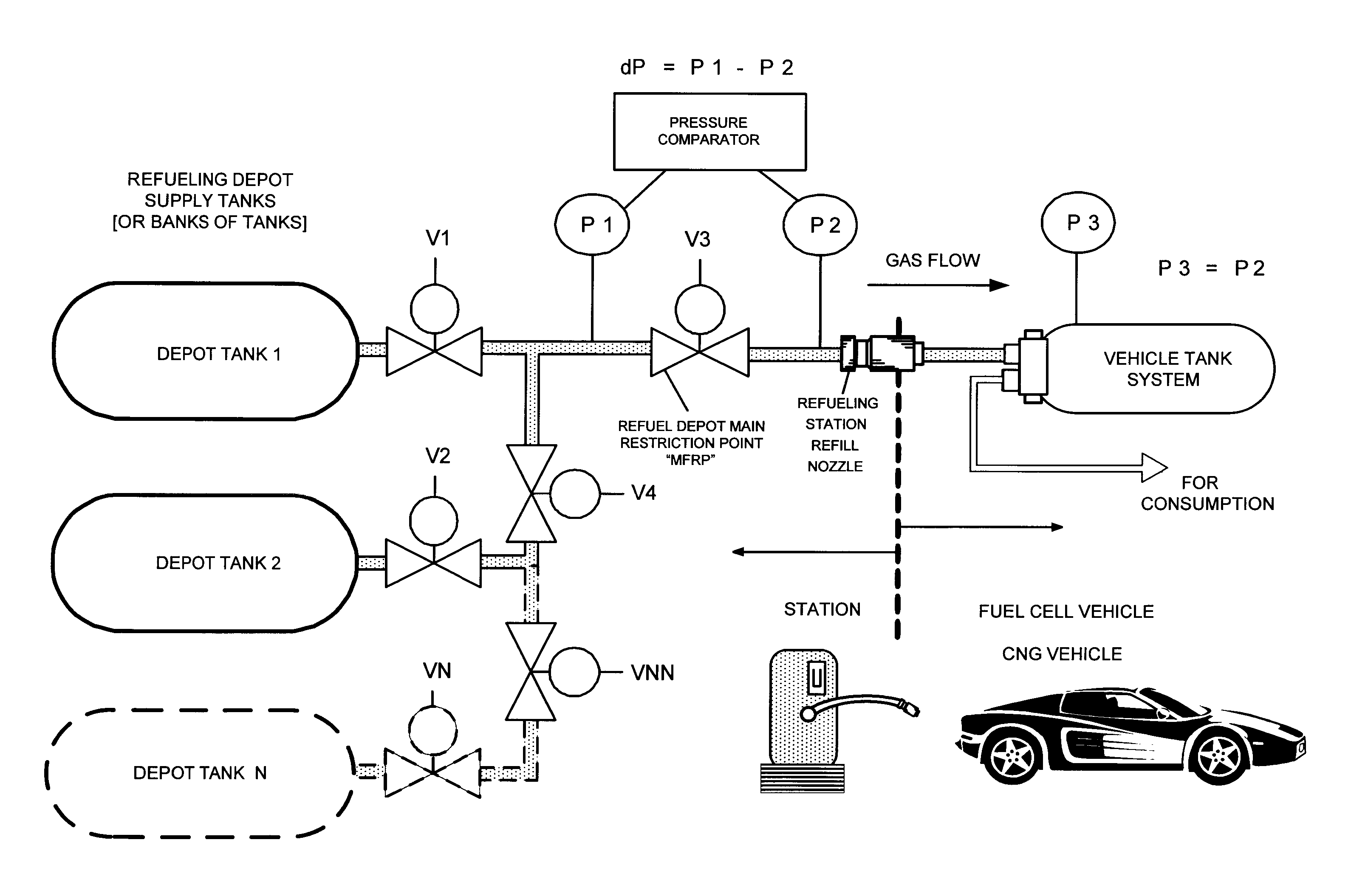
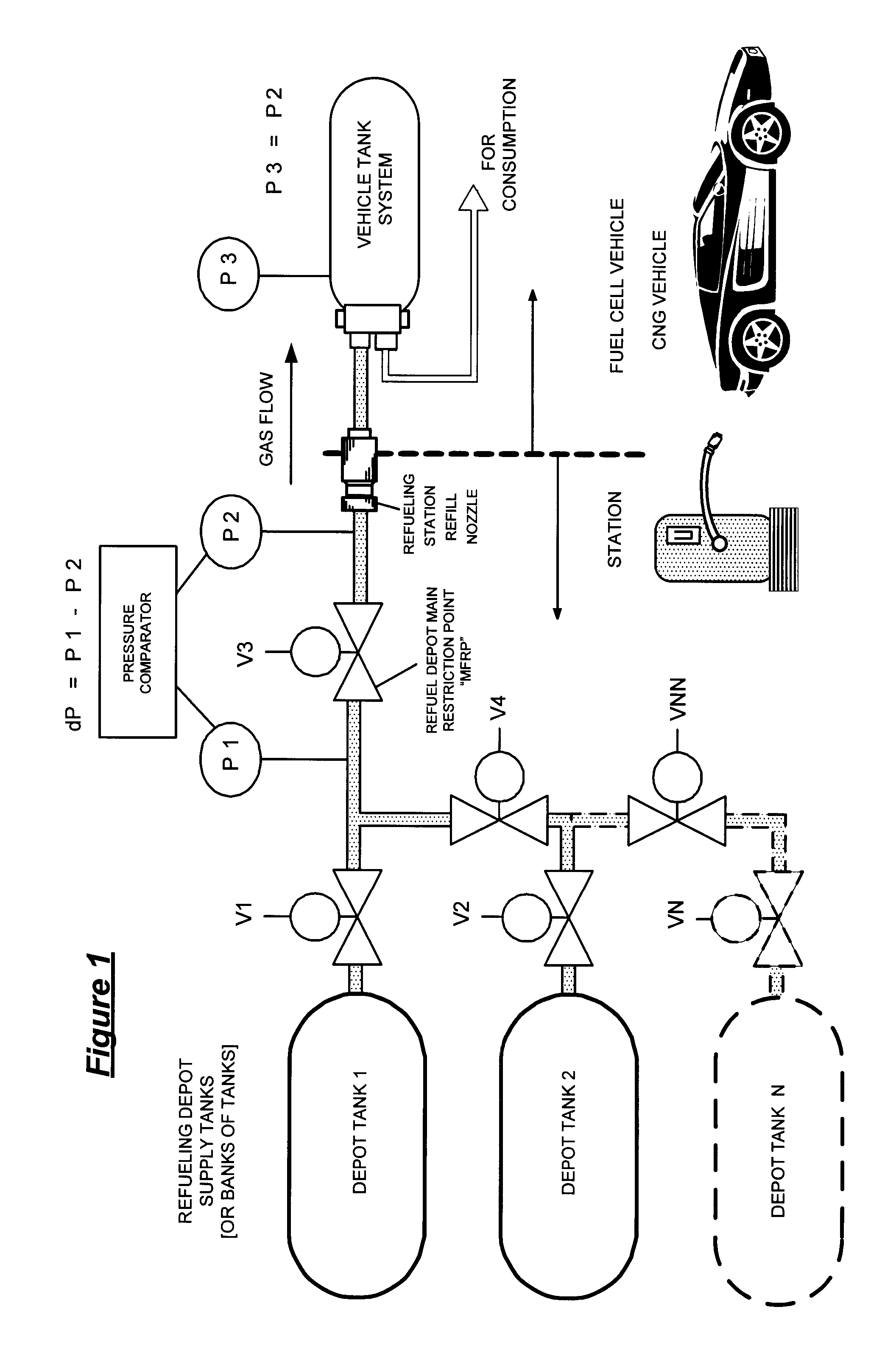
[0022]Example 1 in FIG. 1 illustrates an example of the dP method of the invention utilizing a bank of two tanks (A “bank” may have one or more tanks.) at a refilling station:
[0023]After connection of the refueling hose to the vehicle, refueling starts; valve V3 is opened; valve V1 is opened, then gas from tank 1 at the station flows to the vehicle tank. When dP=P1−P21 is finished and valve V1 is closed. If dP=0 (or approximately 0), and P1 and P2 equal a desired pressure for a full fill P3 (or otherwise), then the refill is complete. Valve V1 and valve V3 are closed. If further gas is required, valve V2 and valve V4 are opened; gas from tank 2 at the station flows to the vehicle tank. When dP=P1−P22 is finished and valve V2 and valve V4 are closed. If dP=0 (or approximately 0), and P1 and P2 equal a desired pressure for a full fill P3 (or otherwise), then the refill is complete. Valve V2, valve V4 and valve V3 are closed. The sequence above is repeated for other tanks N with valves...
example 2
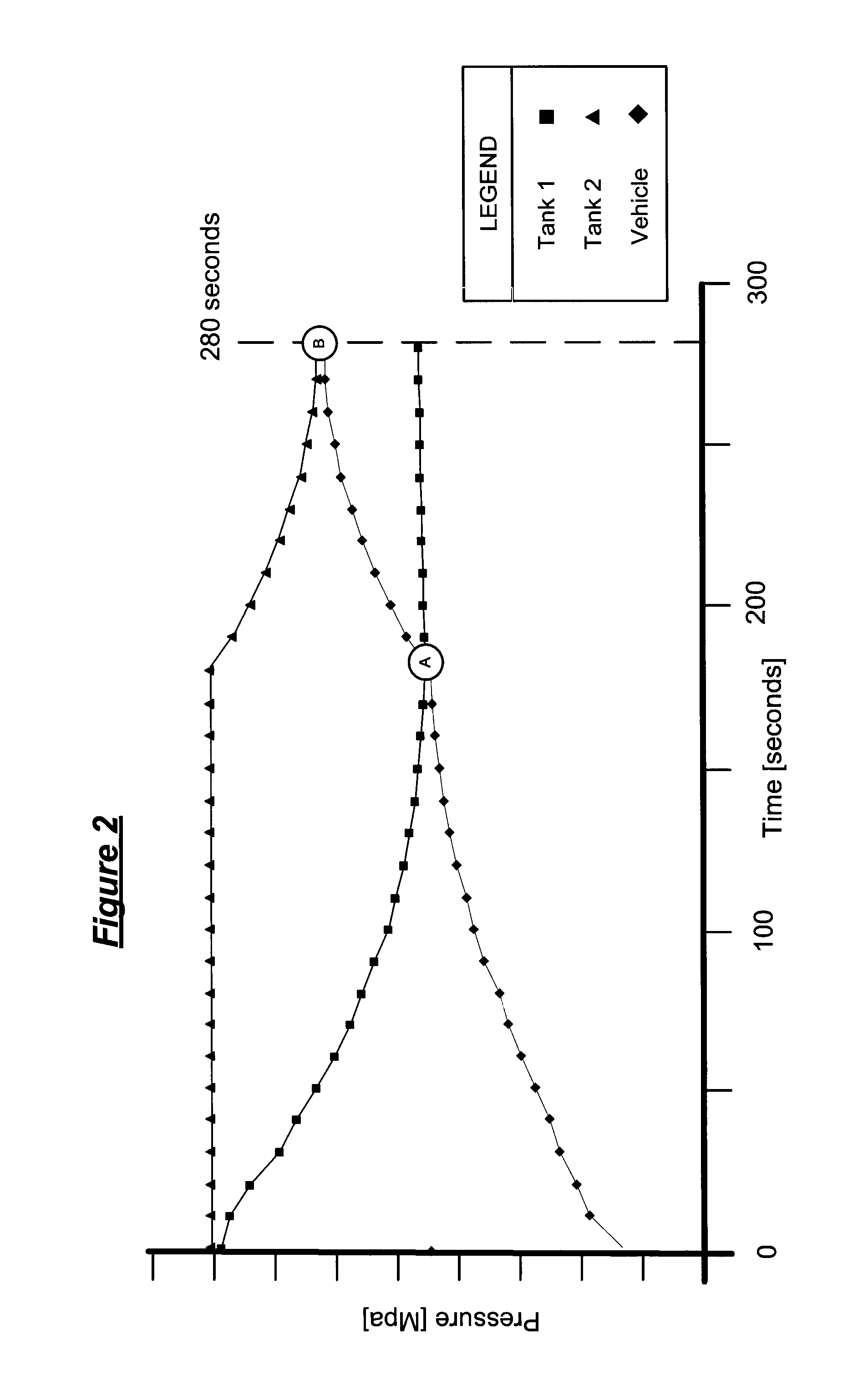
[0024]FIG. 2 is a chart illustrating a test of Example 1. Correct tank switching is provided and sufficient fuel pressure is achieved in the vehicle tank[s] in a reasonable time with little disturbance in refill fluid flow. Pressure in the refill depot bank of tanks, Tank 1 and Tank 2, and the vehicle tank (y-axis) is plotted against time on the x-axis. As tank 1 gas is consumed by the refill, pressure in tank 1 decreases as vehicle tank pressure increases in an almost inverse proportion. When pressure in tank 1 reaches a predetermined limit, at point “A,” the ECU switches to tank 2 whereby pressure in tank 2 equalizes with the vehicle tank pressure at point “B,” whereupon the refill is complete, namely Pvehicle=Ptank 2 or dP=0 at the MFRP. The ECU detects the pressure equalization and terminates the refill process.
example 3
[0025]FIG. 3 illustrates an example of an electronic control unit, ECU, for the dP method wherein sensors measure pressures and determine the differential between P1 and P2 at the main restriction point MFRP (station and vehicle sides of the depot dispenser). The ECU will control tank switching of gas flow from the tanks in the station bank through the vehicle refill gas flow circuit. The pressure difference at the refilling system main restriction point, namely the difference between pressures on opposite sides of the MFRP, station pressure side P1 and vehicle tank pressure side P2, should approach zero at a full consumption of gas from one tank in a bank or at a full fill. An optional main dispensing valve MDV at the front of the refill tanks controls overall on / off flow at the depot. The ECU may also monitor and control gas flow and switching, in parallel or series, or other predetermined sequence of the depot tanks and banks of tanks.
PUM
| Property | Measurement | Unit |
|---|---|---|
| pressure | aaaaa | aaaaa |
| pressure | aaaaa | aaaaa |
| pressure | aaaaa | aaaaa |
Abstract
Description
Claims
Application Information
 - R&D
- Intellectual Property
- Life Sciences
- Materials
- Tech Scout
- Unparalleled Data Quality
- Higher Quality Content
- 60% Fewer Hallucinations
Browse by: Latest US Patents, China's latest patents, Technical Efficacy Thesaurus, Application Domain, Technology Topic, Popular Technical Reports.
© 2025 PatSnap. All rights reserved.Legal|Privacy policy|Modern Slavery Act Transparency Statement|Sitemap|About US| Contact US: help@patsnap.com


