
Controllable input impedance radio frequency mixer

Active Publication Date: 2012-02-21
QORVO US INC
View PDF7 Cites 24 Cited by
  • Summary
  • Abstract
  • Description
  • Claims
  • Application Information

AI Technical Summary

Benefits of technology

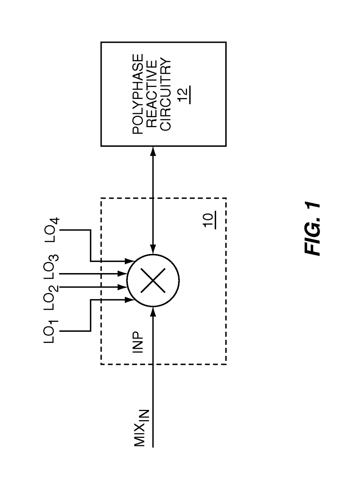
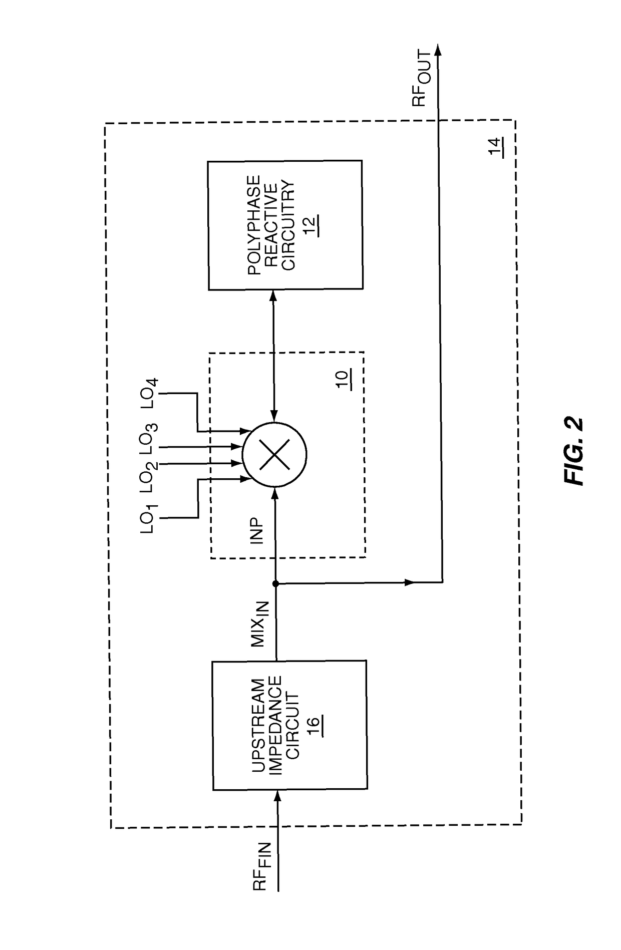
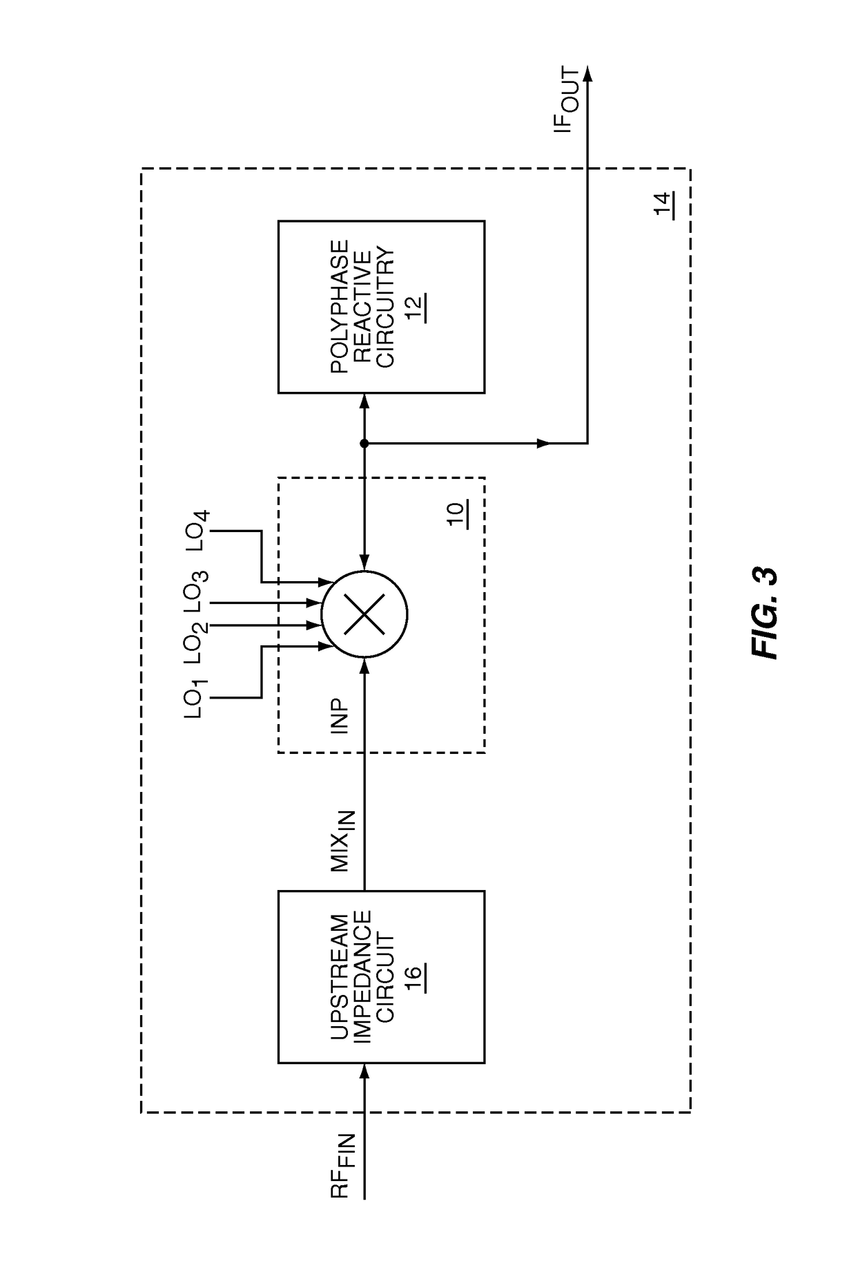
[0005]The present invention relates to a controllable input impedance RF mixer, which when fed from a high impedance source, such as a current source, provides a high quality factor (Q) impedance response associated with an impedance peak. The high-Q impedance response may be used as a high-Q RF bandpass filter in a receive path upstream of down conversion, which may improve receiver selectivity and replace surface acoustic wave (SAW) or other RF filters. The present invention uses polyphase reactive circuitry, such as capacitive elements, coupled to the down conversion outputs of an RF mixer. The RF mixer mixes RF input signals with local oscillator signals to translate the impedance of the polyphase reactive circuitry into the RF input impedance of the RF mixer. The RF input impedance includes at least one impedance peak. The local oscillator signals are non-overlapping to maximize the energy transferred to the polyphase reactive circuitry and eliminate signal losses associated with overlapping phases.
[0006]In some embodiments of the present invention, the polyphase reactive circuitry includes at least one capacitive element. The RF input impedance peak presented to RF input signals at the same phase and frequency of the local oscillator signals may theoretically approach infinity. Losses from the RF mixer, the polyphase reactive circuitry, and the source impedance feeding the RF mixer determine the quality factor (Q) of the impedance peak of the circuit. Alternate embodiments of the present invention may enhance the polyphase reactive circuitry with transconductance circuitry to shift the impedance peak away from the local oscillator frequency to center the bandpass response around a desired receive frequency.

Problems solved by technology

The combination of passive RF mixer circuitry and polyphase reactive circuitry results in low energy loss, which may provide very low voltage mode conversion losses, and low 1 / f noise and low thermal noise.

Method used


Image

  • Controllable input impedance radio frequency mixer
  • Controllable input impedance radio frequency mixer
  • Controllable input impedance radio frequency mixer

Examples


Embodiment Construction

[0031]The embodiments set forth below represent the necessary information to enable those skilled in the art to practice the invention and illustrate the best mode of practicing the invention. Upon reading the following description in light of the accompanying drawing figures, those skilled in the art will understand the concepts of the invention and will recognize applications of these concepts not particularly addressed herein. It should be understood that these concepts and applications fall within the scope of the disclosure and the accompanying claims.

[0032]The present invention relates to a controllable input impedance RF mixer, which when fed from a high impedance source, such as a current source, provides a high quality factor (Q) impedance response associated with an impedance peak. The high-Q impedance response may be used as a high-Q RF bandpass filter in a receive path upstream of down conversion, which may improve receiver selectivity and replace surface acoustic wave (...


PUM


Abstract

The present invention is a controllable input impedance RF mixer, which when fed from a high impedance source, such as a current source, provides a high quality factor (Q) impedance response associated with an impedance peak. The high-Q impedance response may be used as a high-Q RF bandpass filter in a receive path upstream of down conversion, which may improve receiver selectivity and replace surface acoustic wave (SAW) or other RF filters. The present invention uses polyphase reactive circuitry, such as capacitive elements, coupled to the down conversion outputs of an RF mixer. The RF mixer mixes RF input signals with local oscillator signals to translate the impedance of the polyphase reactive circuitry into the RF input impedance of the RF mixer. The RF input impedance includes at least one impedance peak. The local oscillator signals are non-overlapping to maximize the energy transferred to the polyphase reactive circuitry.

Description

[0001]This application claims the benefit of provisional patent application Ser. No. 60 / 910,730, filed Apr. 9, 2007, the disclosure of which is hereby incorporated by reference in its entirety.FIELD OF THE INVENTION[0002]The present invention relates to radio frequency (RF) mixers and filters used in RF communications equipment, such as RF receivers.BACKGROUND OF THE INVENTION[0003]Many typical RF communications systems have RF receivers that need to receive a desired RF signal on a specific RF channel, which is a desired RF channel that has a desired bandwidth and a desired RF center frequency. One function of the RF receiver is to reject any RF signals at frequencies other than those within the desired bandwidth of the desired RF channel; therefore, numerous filtering and signal rejection techniques have been developed to achieve this function. One such technique is called super-heterodyning, in which received RF signals are filtered and then mixed with a local oscillator signal t...

Claims


Application Information

Patent Timeline
IPC IPC(8): H04B1/26
CPCH04B1/109
Inventor MCKAY, THOMAS GREGORY
Owner QORVO US INC
Learn More