
Image processing apparatus and computer-readable storage medium that add marking type information to predetermined image

a technology of image processing and image type, applied in the direction of digital output to print units, instruments, digitally marking record carriers, etc., can solve the problems of source code becoming complex, the efficiency of developing applications may not be improved to an expected level, and the situation becoming complex, so as to simplify the customizing, expansion and the like of functions

Inactive Publication Date: 2012-02-21
RICOH KK
View PDF15 Cites 22 Cited by
  • Summary
  • Abstract
  • Description
  • Claims
  • Application Information

AI Technical Summary

Benefits of technology

This approach simplifies the customization, expansion, and addition of new marking information for image processing, reducing the complexity of source code and development processes, while maintaining independence among filters and activities, thus enhancing memory utilization and processing performance.

Problems solved by technology

But in general, in the case of the platform which is used in common and is provided with the API, the efficiency of developing the application may not be improved to an expected level if the granularity of the interface or the function provided by the platform is not designed appropriately.
For example, if the granularity is too small, the API may be called a large number of times even though the application only provides a simple service, and the source code will become complex.
Particularly in a case where the modules within the platform have a strong dependency relationship with each other, the situation becomes complex because it is not only necessary to add new functions to the platform but it may also be necessary to correct an existing portion.
In addition, when implementing an application which modified a portion (for example, an image input process) of the service provided by the existing application, it is not possible to call the existing application with respect to the portions other than the modified portion.

Method used


Image

  • Image processing apparatus and computer-readable storage medium that add marking type information to predetermined image
  • Image processing apparatus and computer-readable storage medium that add marking type information to predetermined image
  • Image processing apparatus and computer-readable storage medium that add marking type information to predetermined image

Examples


first embodiment

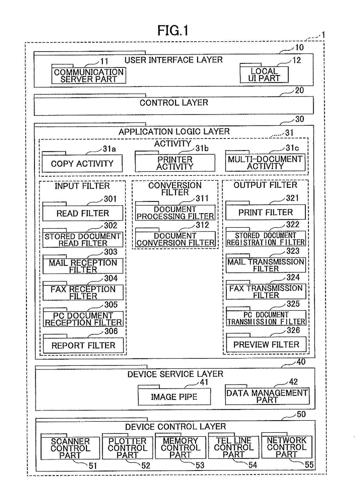
[0044]FIG. 1 is a block diagram showing a software structure of a MFP in a first embodiment of the present invention The MFP is an image processing apparatus which performs a plurality of functions of a printer, a copying apparatus, a scanner, a facsimile apparatus and the like in a single unit.

[0045]As shown in FIG. 1, the software of the MFP 1 is formed by a user interface layer 10, a control layer 20, an application logic layer 30, a device service layer 40, and a device control layer 50. The hierarchical relationship of the layers shown in FIG. 1 is based on the call relationship among the layers. In other words, the upper layer in FIG. 1 basically calls the lower layer.

[0046]The user interface layer 10 is implemented with the function of accepting execution requests of functions such as copy, print, scan and facsimile transmission. For example, the user interface 10 includes a communication server part 11, a local User Interface (UI) part 12, and the like. For example, the comm...

second embodiment

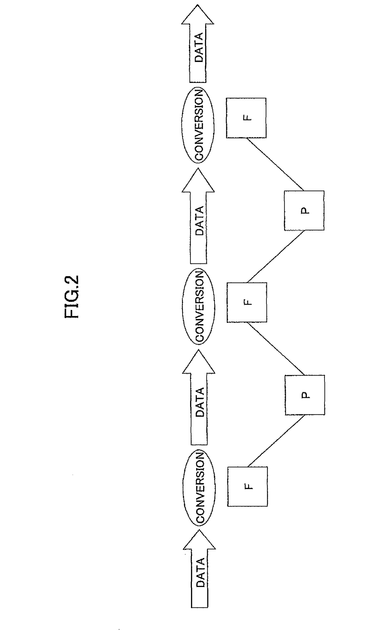
[0109]When new marking information is to be synthesized when making various markings at the time of outputting images on paper, a second embodiment of the present invention enables the new marking information to be added without making considerable modifications to the existing output component (output filter). It is a precondition in this second embodiment that the pipe and filter mechanism is used. A description of the basic structure and operation of the pipe and filter mechanism will be omitted, because the pipe and filter mechanism was described above with respect to the first embodiment.

[0110]FIG. 14 is a diagram showing an example of a software structure of the MFP 1 in this second embodiment of the present invention.

[0111]In FIG. 14, a component of a print filter UI C1 is provided in the user interface layer 10. Components of a copy activity C2, a print filter C3 and an edit filter C4 are provided in the application logic layer 30. Components of a setting information service...


PUM


Abstract

An image processing apparatus includes an input part to input data which is a target of an image processing, an output part to output a result of the image processing, a first filter to control an input process of data from the input part depending on the input part, and a second filter to control an output of data to the output part depending on the output part. A marking type information which is to be added to a predetermined image is specified with respect to the second filter, a marking image is created based on the marking type information, and the marking image is synthesized with respect to an image which is output from the output service. The second filter instructs output of an image with respect to the output service. An application is formed by connecting the first filter and the second filter.

Description

BACKGROUND OF THE INVENTION[0001]1. Field of the Invention[0002]The present invention generally relates to image processing apparatuses and application executing methods, and more particularly to an image processing apparatus having a plurality of types of input parts for inputting data that is a target of an image processing and a plurality of types of output parts for outputting a result of the image processing, and to an application executing method therefor.[0003]2. Description of the Related Art[0004]Recently, in image processing apparatuses such as printers, copying apparatuses, scanners, facsimile apparatuses and Multi Function Peripherals (MFPs) which perform functions of a plurality of such apparatuses in a single unit, the memory space is limited but a Central Processing Unit (CPU) is provided similarly to a general-purpose computer in order to perform various functions under the control of applications (or application programs).[0005]For example, an image processing appar...

Claims


Application Information

Patent Timeline
Patent Type & Authority Patents(United States)
IPC IPC(8): H04N1/40
CPCH04N1/32144H04N2201/0094H04N2201/3246
Inventor NAGATA, TADASHI
Owner RICOH KK
Learn More