Implantable pump with infinitely variable resistor
a technology of infinite resistor and implantable pump, which is applied in the direction of intravenous devices, medical preparations, other medical devices, etc., can solve the problems of severe side effects, difficult injections, and pain for patients of this type, and achieve the effect of reducing reducing the size of the passageway, and increasing or decreasing the flow rate of active substances
- Summary
- Abstract
- Description
- Claims
- Application Information
AI Technical Summary
Benefits of technology
Problems solved by technology
Method used
Image
Examples
first embodiment
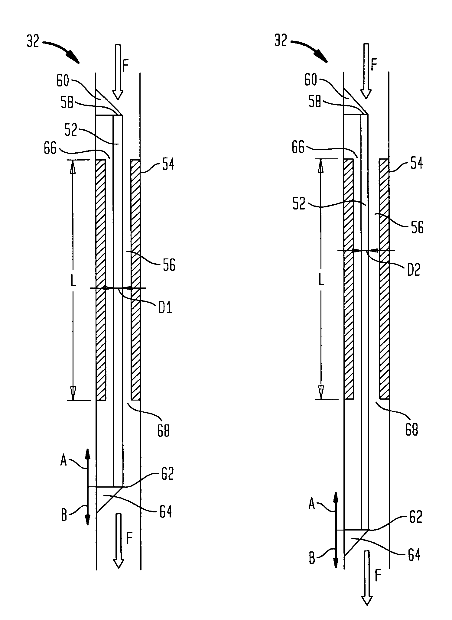
[0082]FIGS. 9, 10a and 10b show a first example of the first embodiment resistor 32, where elastic filament 52 is located concentrically in resistor capillary 54. This configuration forms a ring-shaped flow channel 56 through which fluid flows in a direction shown by arrow F. As is best shown in FIG. 10a, filament 52 includes a first end 58 attached to a stationary attachment 60, and a second end 62 attached to a movable attachment 64. Resistor 32 also has an effective length L extending between capillary entrance 66 to exit 68, and an initial diameter D1 (i.e.—2 times its radius R1). Additionally, capillary 54 has a diameter D3 (i.e.—2 times its radius R3). This will be similar throughout in the various other capillaries discussed herein.
[0083]In this example, movable attachment 64 is capable of moving in the opposite longitudinal directions shown by arrows A and B, while attachment 60 remains stationary. In operation, movement of attachment 64 in the direction of arrow B increases...
second embodiment
[0120]In operation of this second embodiment, fluid is introduced into hollow interior 304 in the direction indicated by arrow 314. Upon the sufficient build up of pressure created by the flow of the fluid, the closed end 312 design of second member 308 forces the fluid to move in the direction indicated by arrow 315 (best shown in FIG. 17) and through the flow channel defined by the threaded configuration of the two members 320, 308. The degree of overlap of the two threaded geometries determines the hydraulic resistance, and thus the flow rate of the fluid. Therefore, the high overlap shown in FIG. 16 would result in a lesser flow rate than that of the low overlap depicted in FIG. 17. Nevertheless, the fluid ultimately emerges from the resistor design as illustrated by arrows 316. It is envisioned that in other examples in accordance with this embodiment of the present invention the shapes of the two members may vary, as can the particular thread design employed.
[0121]In a third e...
PUM
 Abstract
Description
Claims
Application Information
 - R&D
- Intellectual Property
- Life Sciences
- Materials
- Tech Scout
- Unparalleled Data Quality
- Higher Quality Content
- 60% Fewer Hallucinations
Browse by: Latest US Patents, China's latest patents, Technical Efficacy Thesaurus, Application Domain, Technology Topic, Popular Technical Reports.
© 2025 PatSnap. All rights reserved.Legal|Privacy policy|Modern Slavery Act Transparency Statement|Sitemap|About US| Contact US: help@patsnap.com


