Field programmable gate array

a gate array and field technology, applied in the field of efficient implementation of dsp functions, can solve the problems of inconvenient fixed inflexible hardware architecture of dsp processors, and limited performance of dsp processors, so as to achieve efficient cascade and waste clock cycles.

Active Publication Date: 2012-02-07
MINERAL LASSEN
View PDF5 Cites 17 Cited by
  • Summary
  • Abstract
  • Description
  • Claims
  • Application Information

AI Technical Summary

Benefits of technology

[0016]The present invention aims at providing a versatile DSP block architecture, which will cater to a large section of DSP applications. In particular, not only does the present invention allow an extra coefficient to be added without consuming an extra clock cycle, but it also allows for two or more DSP blocks to be efficiently cascaded. This cascading proves highly beneficial for designs having chains of MACs for e.g., a n-tap filter (where n is only limited by the number of DSP blocks in one column of the chip) can be completely implemented in the DSP blocks using the cascade feature. An added feature is the presence of a dynamic SMUX signal, which allows the user to start a new accumulation cycle without resetting the accumulator and thereby wasting a clock cycle.
[0017]To overcome the aforesaid drawbacks, the present invention provides a versatile embedded core for implementation of DSP applications in FPGA in an area-efficient manner. It also provides efficient implementations of designs having series of MACs, for e.g., an n-tap filter where n depends upon the number of DSP blocks used in one column of the chip. The architecture disclosed herein enables efficient implementation of the DSP equation by facilitating addition of an extra coefficient without consuming an extra clock cycle, and enables cascading of the DSP blocks.
[0018]To achieve the aforementioned advantages, the present invention provides an efficient implementation of DSP functions in a FPGA using one or more computational blocks, each block including:

Problems solved by technology

Although DSP processors are programmable through software, yet the DSP processor hardware architecture used is not flexible.
Therefore, the performance of the DSP processors is limited by fixed hardware architecture such as bus performance bottlenecks, a fixed number of multiply accumulate (MAC) blocks, fixed memory, fixed hardware accelerator blocks, and fixed data widths.
Further the DSP processor's fixed hardware architecture is not suitable for certain applications that might require customized DSP function implementations.
The MAC operation is usually the performance bottleneck in most DSP applications.

Method used


Image

  • Field programmable gate array
  • Field programmable gate array
  • Field programmable gate array

Examples


Embodiment Construction

[0050]Embodiments of the present invention are described below with an 18×18 multiplier, a 2:1 multiplexer, and accumulators as an example to aid better understanding. The invention is however not restricted by the sizes shown in any of the figures and any person skilled in the art can very well extend the invention to different sizes or proportions.

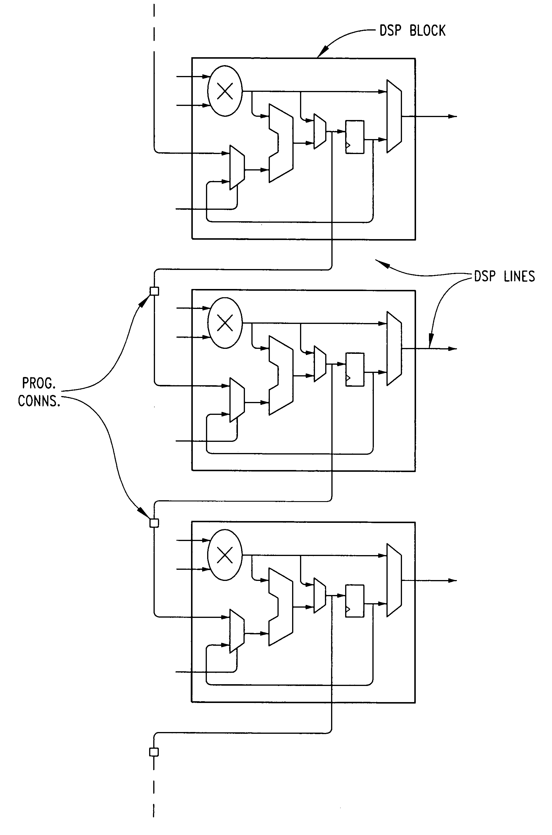
[0051]FIG. 3 discloses the proposed architecture of the DSP block containing an 18×18 multiplier (26) followed by an accumulator (28) with the second input of the accumulator (28) either being a feedback or another dynamic input obtained from a multiplexer (27). The register (29) receives its inputs from the accumulator (32) and provides a feedback to the multiplexer (27) as well as provides the final input.

[0052]FIG. 4 discloses an embodiment of the proposed architecture of the DSP block containing an 18×18 multiplier (30) followed by an accumulator (32) with the second input of the accumulator (32) either being a feedback or another dy...


PUM


Abstract

An efficient implementation of DSP functions in a field programmable gate array (FPGA) using one or more computational blocks, each block having of a multiplier, an accumulator, and multiplexers. The structure implements most common DSP equations in a fast and a highly compact manner. A novel method for cascading these blocks with the help of dedicated DSP lines is provided, which leads to a very simple and proficient implementation of n-stage MAC operations.

Description

BACKGROUND OF THE INVENTION[0001]1. Field of the Invention[0002]The present invention relates to an efficient implementation of DSP functions in a field programmable gate array (FPGA).[0003]2. Description of the Related Art[0004]Digital signal processing (DSP) has traditionally been done using enhanced microprocessors. Although DSP processors are programmable through software, yet the DSP processor hardware architecture used is not flexible. Therefore, the performance of the DSP processors is limited by fixed hardware architecture such as bus performance bottlenecks, a fixed number of multiply accumulate (MAC) blocks, fixed memory, fixed hardware accelerator blocks, and fixed data widths. Further the DSP processor's fixed hardware architecture is not suitable for certain applications that might require customized DSP function implementations.[0005]FPGAs, on the other hand, can provide a fast, cost effective solution to many of today's complex demands for implementing DSP functionali...

Claims


Application Information

Patent Timeline
Patent Type & Authority Patents(United States)
IPC IPC(8): G06F7/38
CPCG06F7/57G06F15/7867
Inventor MINZ, DEBOLEENADIGARI, KAILASH
Owner MINERAL LASSEN
Why Eureka
Try Eureka