
Method and apparatus for transparent shelves and drawers for kitchen cabinets

a technology for kitchen cabinets and drawers, applied in the field of cabinets, can solve problems such as difficulty in accessing items at the rear of drawers

Inactive Publication Date: 2012-02-07
LAZENBY JAMES W
View PDF46 Cites 25 Cited by
  • Summary
  • Abstract
  • Description
  • Claims
  • Application Information

AI Technical Summary

Benefits of technology

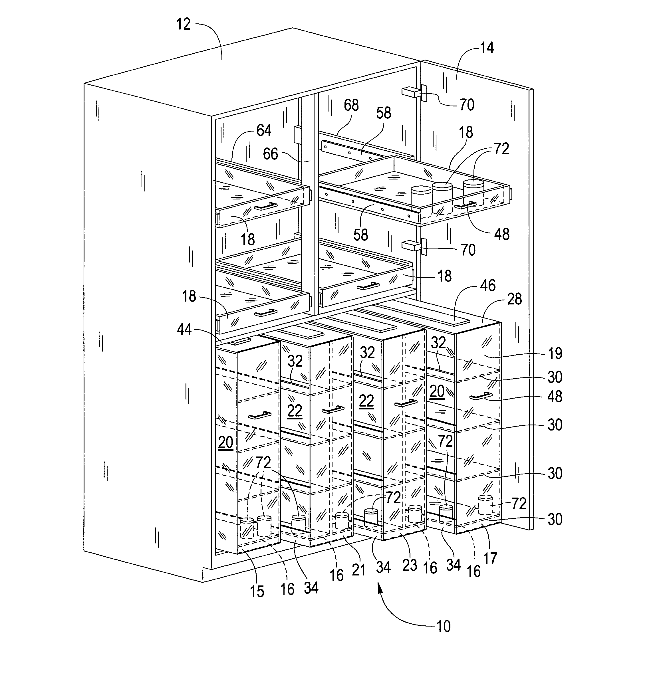
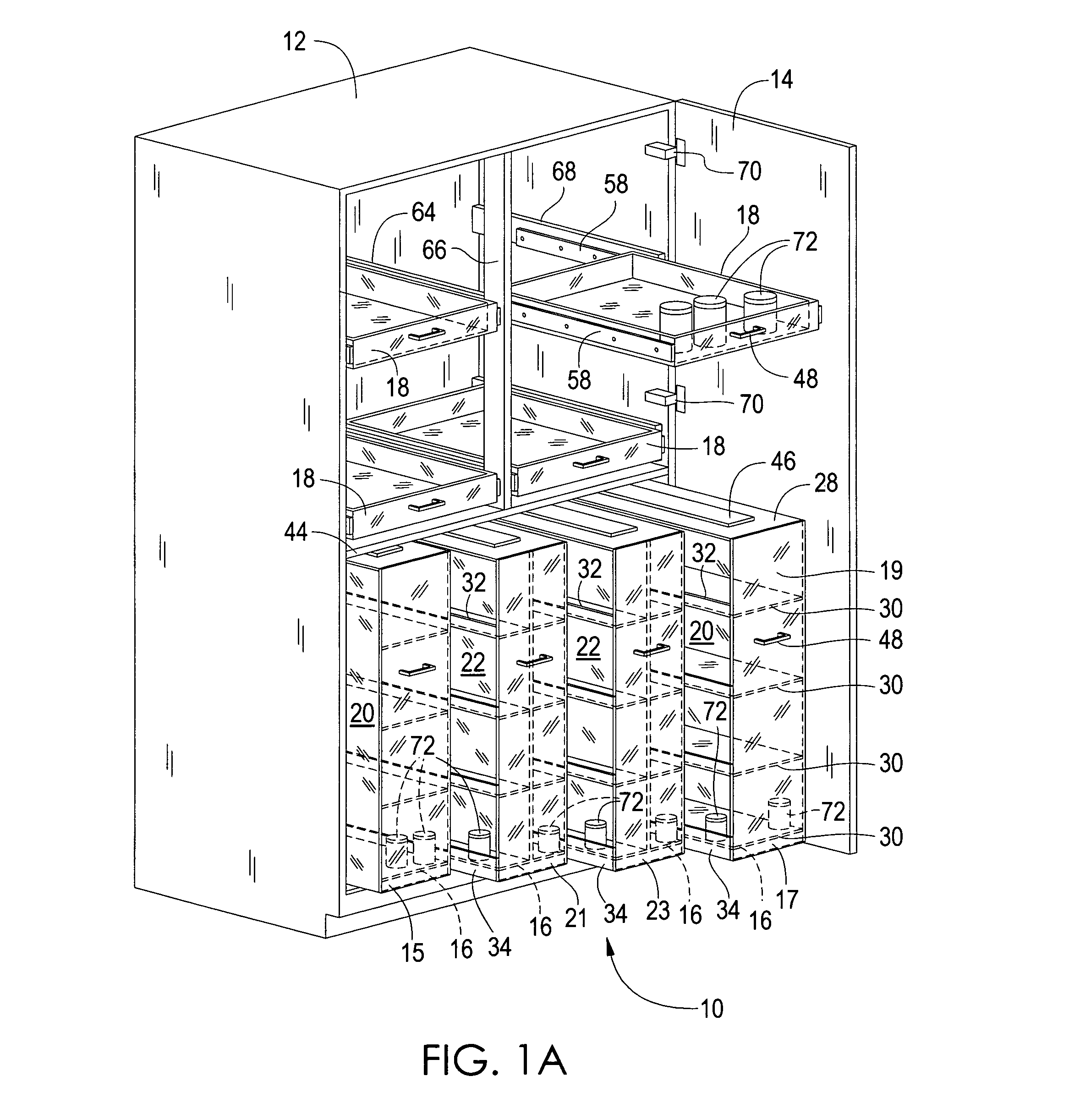
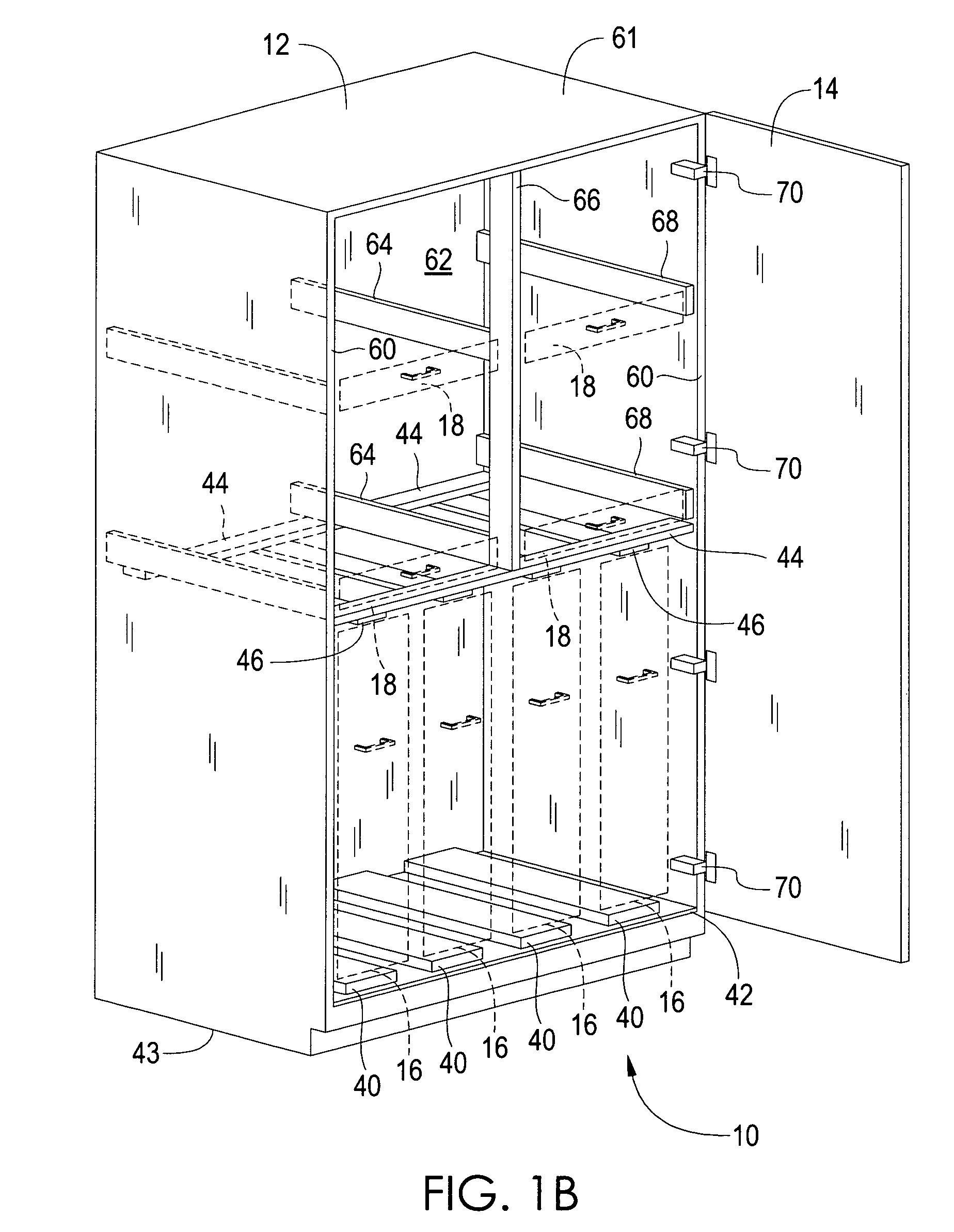
[0007]The system is a combination of vertical rollout units made using any transparent material, such as acrylic, that can be cut and fitted together and then fused to make a strong, self supporting lightweight unit. Each unit is then supported with two heavy duty drawer guides placed at the base or top to carry vertical loads and at least one horizontal heavy duty guide at the opposite end to laterally stabilize the unit. Conventional drawer guides are used, and any conventional guide could be used that will carry the required load. By having a transparent unit and shelves only wide enough to typically support most pantry items, items stored are only one deep and can be easily seen without even rolling out a unit, and then can be easily reached by pulling out the appropriate unit containing the desired item. Clear rollout drawers are also part of the system and would be used in pairs above the rollout units. Drawers are used above rollout units in pairs as they have the advantage, by being clear, of seeing items through the bottom of the drawer, and by having the drawers in pairs, someone can extend one drawer at a time and reach to the back of each drawer from the sides, and this gives more drawer usage than full width conventional shelves. As mentioned earlier, full width rollout drawers above shoulder height make it difficult to access items at the rear of the drawer.

Problems solved by technology

As mentioned earlier, full width rollout drawers above shoulder height make it difficult to access items at the rear of the drawer.

Method used


Image

  • Method and apparatus for transparent shelves and drawers for kitchen cabinets
  • Method and apparatus for transparent shelves and drawers for kitchen cabinets
  • Method and apparatus for transparent shelves and drawers for kitchen cabinets

Examples


Embodiment Construction

[0023]The following discussion describes in detail at least one embodiment of the present invention. This discussion should not be construed, however, as limiting the present invention to the particular embodiments described herein since practitioners skilled in the art will recognize numerous other embodiments as well. For a definition of a complete scope of the invention the reader is directed to the appended claims. FIGS. 1 through 9 illustrate the present invention wherein a method and apparatus for a system of rollout shelves and drawers for a kitchen pantry cabinet is disclosed.

[0024]Turning to FIG. 1A, therein is shown the present invention 10 comprising a conventional kitchen pantry cabinet 12 having front side doors 14 with hinges 70 thereon (while only one right door is shown in this view for visual clarity, typically the cabinet would have a left and right door thereon). The present invention 10 comprises a system of rollout shelf units 16 (sometimes referred to herein as...


PUM


Abstract

A transparent rollout pantry organizing system for kitchen cabinets has at least two rollout shelf units that are constructed of planar clear sheet material that is cut and fused together to form a rigid structural shape with shelves having heavy duty drawer guides fastened to the rollout unit which can be extended out of the pantry cabinet so that items can be easily accessed, and having at least one pair of side by side drawers above the rollout units also made of clear material used for the rollout units. By using clear material, items on upper shelves can be seen through the drawer bottoms, and by using the drawers in pairs, items on upper drawers at the rear of the drawer can be easily accessed by extending one drawer at a time and reaching over the sides.

Description

RELATED APPLICATIONS[0001]This application is a Continuation-in-Part of U.S. patent application Ser. No. 12 / 288,899 filed on Oct. 25, 2008 now abandoned.BACKGROUND OF THE INVENTION[0002]1. Field of the Invention[0003]The present invention relates generally to cabinets and, more particularly, is concerned with a method and apparatus for transparent rollout cabinet drawers and shelves.[0004]2. Description of the Prior Art[0005]Tall pantry cabinets are typically designed with fixed shelves, full width rollout shelves, and multiple foldout door panels with shelves or individual rollout shelf units with individual cabinet panel fronts. In tall pantry cabinets using the aforementioned designs, the problems normally found are as follows: With fixed or even adjustable shelves, only the items in the front of a typical 24 inch deep cabinet can be seen or accessed very easily. When full width rollout shelves are used, it is difficult to see items near the rear as labels on cans, or other food ...

Claims


Application Information

Patent Timeline
IPC IPC(8): A47B88/00
CPCA47B88/00A47B67/04A47B88/42A47B88/90
Inventor LAZENBY, JAMES W.
Owner LAZENBY JAMES W
Learn More