Eureka AIR delivers breakthrough ideas for toughest innovation challenges, trusted by R&D personnel around the world.

Paint coating system

a coating system and paint technology, applied in the field of paint coating systems, can solve the problems of long changing operation time, considerable productivity degradation, difficult mechanisms, etc., and achieve the effect of reducing the cost of the coating line as a whole, reducing the cost of the coating line, and prolonging the service life of the components

Inactive Publication Date: 2012-02-07
ABB IND
View PDF18 Cites 1 Cited by
  • Summary
  • Abstract
  • Description
  • Claims
  • Application Information

AI Technical Summary

Benefits of technology

[0018]In view of the above-discussed problems with the prior art, it is an object of the present invention to provide a paint coating system adopting a cartridge changer which is reduced in weight and operative smoothly and efficiently in replacing paint cartridges by the cartridge changer.
[0022]As a consequence, the cartridge changer can be significantly reduced in weight of the swing arm to lessen loads which are imposed on various moving parts, guaranteeing higher working speed and improved braking ability. That is to say, the cartridge changer can complete a cartridge replacing operation in a shorter time period without degradations in control accuracy, achieving improvements in productivity.
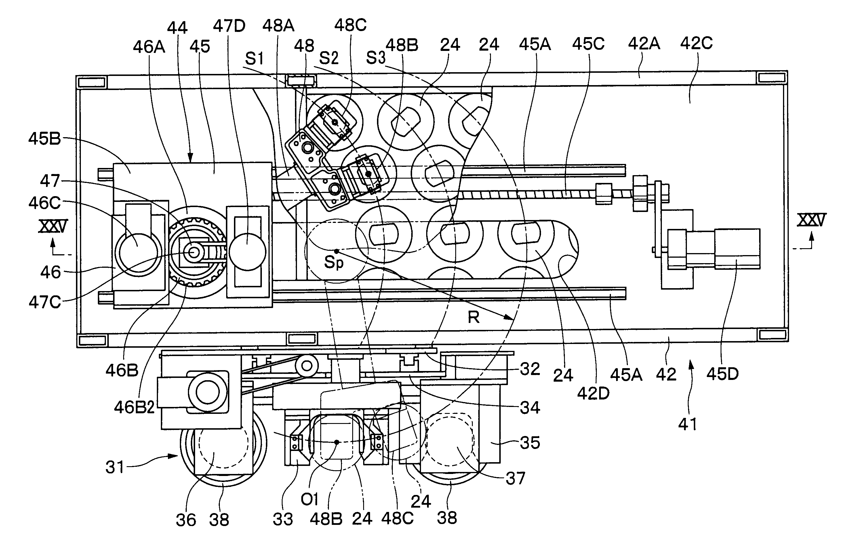
[0029]Thus, the cartridge changer is capable of dismantling a used paint cartridge from the common body of the coater unit which is fixedly retained at the changing position of the atomizing head changing and washing device or mounting a replenished paint cartridge. In this case, a greater number of paint cartridges can be set on the mount deck simply by increasing the number of the arcuate cartridge rows on the mount deck.
[0032]As a consequence, an atomizing head and a paint cartridge can be dismantled from or mounted on the common body very smoothly to guarantee an elongated service life for these components. Besides, the installation work for the robot device, the installation and possessing work for the atomizing head changing and washing device or the cartridge changer can be carried out efficiently in a facilitated manner. In addition, the cost of a coating line as a whole can be cut down to a significant degree.

Problems solved by technology

Due to heavy weight, the two transfer mechanisms are difficult to start and stop a transfer action speedily.
That is to say, the cartridge transfer mechanisms of this type are necessarily required to lower the transfer speed in order to transfer a paint cartridge accurately to a specific position, resulting in a longer changing operation time and a considerable degradation in productivity.
However, in the case of a robot device which is in use for paint coating operations, with regard to the repeated positioning accuracy in motion control such as moving, stopping, posture and the like of a coater unit which is mounted on a distal end of a robot arm, there is inevitably an error of several millimeters.
Therefore, if the changing operation is carried out depending upon the accuracy of motion control on the part of the robot device alone, this deviation from the predetermined changing position may result in exertion of a forcible load between a common body and the atomizing head or the paint cartridge, shortening the service life of the coater unit by repeated abrasive and damaging contact.
Further, in the case of the paint coating system according to Patent Literature 3, a coater unit which is attached on a robot arm is not equipped with a replaceable paint atomizing head.
Therefore, in this case, there is a problem of low productivity because it is impossible to carry out a paint washing operation and a coating operation simultaneously.
In addition, washer is not provided for washing a head portion of a coater unit.
Furthermore, the paint coating system according to Patent Literature 3, a rotary table on which paint cartridges are placed is rotated by a motor while a cartridge gripper is arranged to move linearly, requiring a large space for installation and a mechanism of complicate construction.

Method used


Image

  • Paint coating system
  • Paint coating system
  • Paint coating system

Examples


Embodiment Construction

[0078]Hereafter, with reference to FIGS. 1 through 44, the paint coating system of the present invention is described more particularly by way of its preferred embodiment which is applied as a vehicle body painting system, for example.

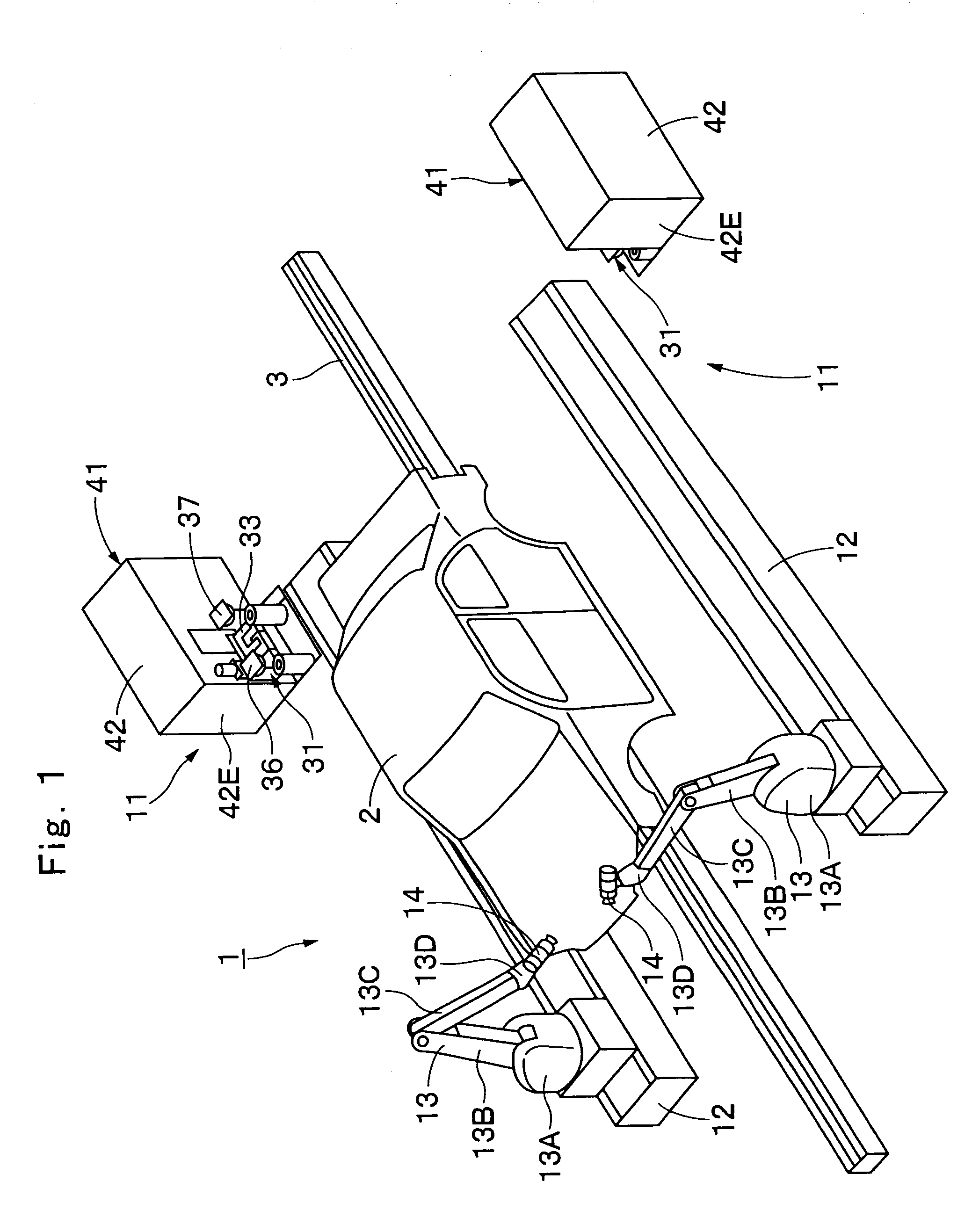
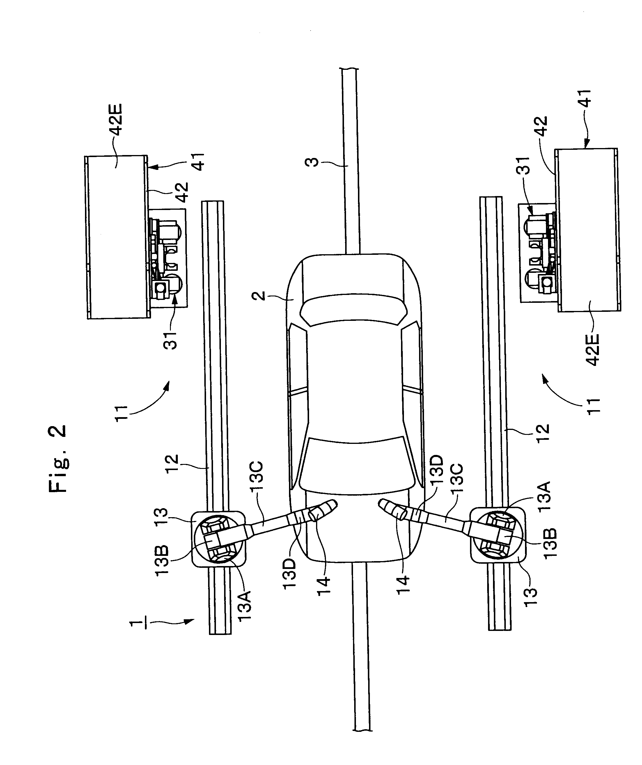
[0079]In FIGS. 1 and 2, indicated at 1 is a coating line for coating a vehicle body 2. Moreover, at the half way of the conveyer 3, paint coating system 11, which will be described hereinafter, are located on the opposite side of the conveyer 3.

[0080]Indicated at 11 are paint coating systems which are located at the half way and cooperatively on the opposite sides of the conveyer 3. Each one of the paint coating systems 11 is largely constituted by a robot device 13, a coater unit 14, an atomizing head changing and washing device 31, and a cartridge changer 41, which will be described hereinafter.

[0081]Designated at 12 are tracking rails which are located in predetermined transversely spaced positions on the opposite side of the conveyer 3 in parallel ...


PUM


Abstract

A cartridge changer (41) is composed of a swing arm (48) with a cartridge gripper (48B) for gripping a paint cartridge (24), and an arcuate moving portion (46) for putting the swing arm (48) in swinging movements in a horizontal plane. The cartridge changer (41) is adapted to pick up a replenished paint cartridge (24) on the mount deck (42) by the cartridge gripper (48B) and transfer the swing arm (48) to a changing position “O” by the arcuate moving portion (46). By the operation, a used paint cartridge (24′) will be replaced by the replenished paint cartridge (24) between the mount deck (42) and a common body (15) which is located in the changing position “O” of the atomizing head changing and washing device (31).

Description

TECHNICAL FIELD[0001]This invention relates to a paint coating system particularly suitable for use, for example, in coating vehicle bodies, furniture, electric appliances and the like.BACKGROUND ART[0002]Generally, paint coating systems in use for painting vehicle bodies and the like are largely constituted by a robot device with an articulated arm, and a coater unit mounted on a distal end of the robot arm of the robot device and provided with an atomizing head for spraying atomized paint particles.[0003]Among paint coating systems of this sort, there is a system providing a paint cartridge replenished by a paint which will be supplied to an atomizing head of the coater unit and can be replaceably attached to a common body which is mounted on a distal end of a robot arm of the robot device (see, for example, Patent Literature 1: Japanese Patent Laid-Open No. 2000-176333).[0004]More particularly, the paint coating system described in the above-mentioned Patent Literature 1 employs ...

Claims


Application Information

Patent Timeline
Patent Type & Authority Patents(United States)
IPC IPC(8): B05B15/02B05B3/00A62C31/00B05B5/00
CPCB05B3/1057B05B5/04B05B12/1463B25J15/0019B25J15/0491B05B5/0407B05B9/047B05B13/0452B05B15/061B05B15/62
Inventor UMEZAWA, TOKUOMATSUDA, HIDETSUGUKUROMOTO, MASAHARUSAKATA, YUTAKA
Owner ABB IND
Why Eureka
Eureka Blog
Learn More