Tankless electric water heater with efficient thermal transfer

a efficient technology, applied in the field of tankless electric water heaters, can solve the problems of high cost, large tank-based water heaters, waste of energy and money, etc., and achieve the effects of low back pressure, high energy efficiency and simple design

Inactive Publication Date: 2012-01-31
HOLLIS JEREMY LEE
View PDF26 Cites 0 Cited by
  • Summary
  • Abstract
  • Description
  • Claims
  • Application Information

AI Technical Summary

Benefits of technology

[0013]An electrically heated tankless water heater is claimed that provides high energy efficiency and low back-pressure in a compact and simple design that is inexpensive to produce. The claimed tankless water heater includes a heating element located within a flow-through container. Each portion of the surface of the heating element is in a directly facing and physically unobstructed relationship with a corresponding portion of the container walls, creating therebetween a flow passage that the water is required to traverse as it flows through the container.
[0014]The entire surface of the heating element is exposed to the water, thereby maximizing the efficiency of heat transfer to the water. All generated heat is forced to flow into the water, thereby minimizing heat loss to the environment. And because most of the flow passage is narrow and unobstructed, all of the water is brought into efficient and direct thermal contact with the surface of the heating element, while at the same time the water is maintained in a laminar flow so as to minimize back-pressure. The heater of the present invention thereby creates a laminar flow of water while at the same time bringing all of the water into efficient and direct thermal contact with the heating element.
[0015]The width of the flow passage is selected so as to minimize the volume of water that is heated by each unit portion of the heater element surface, while at the same time providing sufficient flow passage width to avoid undue drag and / or turbulence due to viscous interaction between the water and the boundaries of the flow passage.
[0023]Preferred embodiments further include protrusions that extend outward from the heating element so as to increase thermal contact between the heating element and the fluid as the fluid flows through the flow-through container. And in some of these embodiments the protrusions are aligned with the fluid flow so as to minimize turbulence in the fluid flow.
[0030]Preferred embodiments further include protrusions that extend outward from the heating element so as to increase thermal contact between the heating element and the water as the water flows through the flow-through container. And in some of these embodiments the protrusions are aligned with the water flow so as to minimize turbulence in the water flow.

Problems solved by technology

However, tank-based water heaters suffer from several disadvantages.
They are generally required to maintain large quantities of water at elevated temperatures for extended periods of time between use, and this wastes energy and money.
Tank-based water heaters are typically large, difficult to site, and expensive, so that even very large plumbing systems usually include only a few, or typically only one, tank-based water heater, which is often located in a basement or other non-central location.
This means that hot water must be piped over significant distances so as to serve all desired locations in a plumbing system, thereby wasting more energy and money, and requiring users to run the water for several seconds or minutes before hot water arrives.
In addition, a tank-based water heater has a finite water capacity, and can require considerable time to replenish its hot water reservoir once it is exhausted.
This can be a major inconvenience for someone who wishes to bathe or otherwise use hot water after the capacity of a tank-based water heater has been exhausted.
The situation is even worse if the user is in the process of bathing when the hot water runs out.
Some tankless water heaters use oil or gas to heat water, but these systems suffer from many of the same disadvantages as tank-based water heaters.
They are typically large, difficult to site, and expensive, so that even very large plumbing systems usually include only a few, or typically only one, oil or gas heated tankless water heater, typically located in a basement or other non-central location.
As with tank-based water heaters, this means that hot water must be piped over significant distances so as to serve all desired locations in a plumbing system, thereby wasting energy and money and requiring users to wait for arrival of hot water.
However, electricity is generally more costly than oil or gas, so it is critical that an electric, tankless water heater use energy as efficiently as possible.
Nevertheless, at least some of the heat generated by the heating element is inevitably lost to the environment without passing through the water, thereby wasting energy and increasing the operating cost.
However, this approach can waste energy due to uneven exposure of different regions of the heating element to the surrounding water.
However, the turbulence creates added back-pressure in the plumbing system, which must be overcome by enlarging the cross-sectional flow-through area of the heating chamber, leading to larger water heaters.
Electric tankless water heaters that encourage laminar water flow through the heating chamber provide lower back-pressures, but are generally less energy efficient, because only some of the water is brought into direct contact with the heating element.
These units therefore require larger heating elements and correspondingly larger heating chambers.
Furthermore, many electric tankless water heaters, although small, are complex in design and expensive to produce, thereby limiting the number of units that can be deployed in a plumbing system without exceeding the available budget.

Method used


Image

  • Tankless electric water heater with efficient thermal transfer
  • Tankless electric water heater with efficient thermal transfer
  • Tankless electric water heater with efficient thermal transfer

Examples


embodiment 200

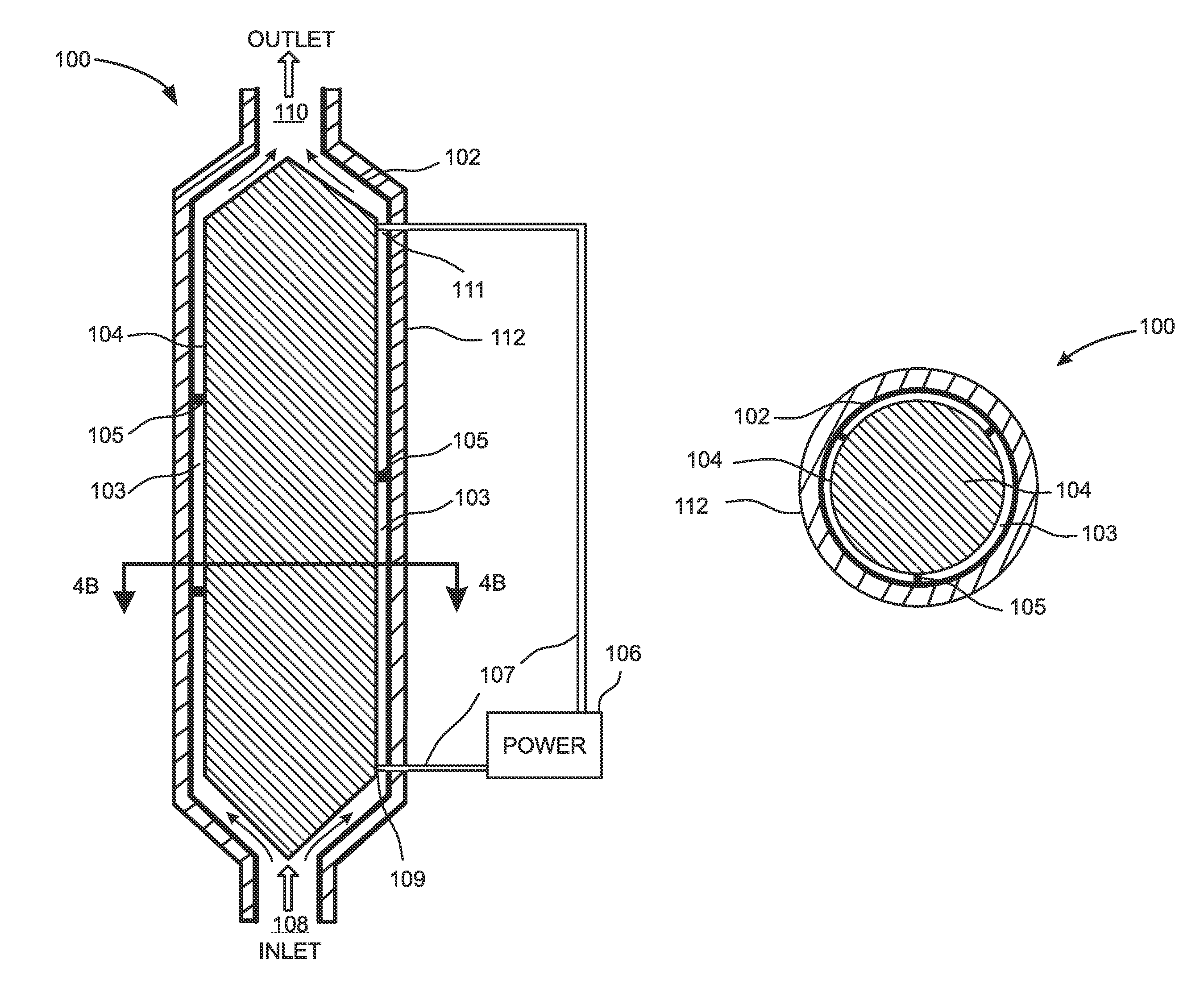
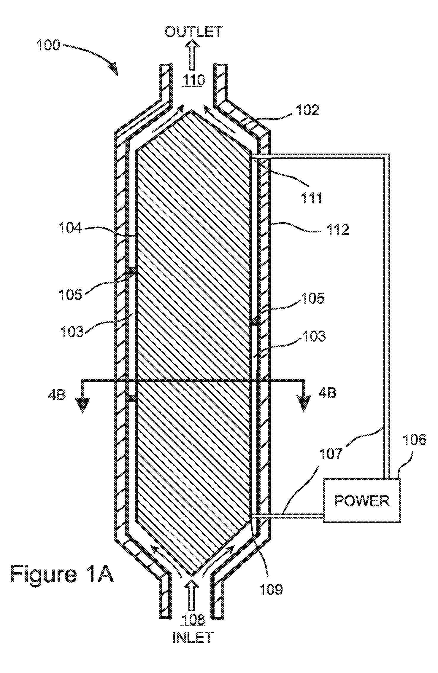
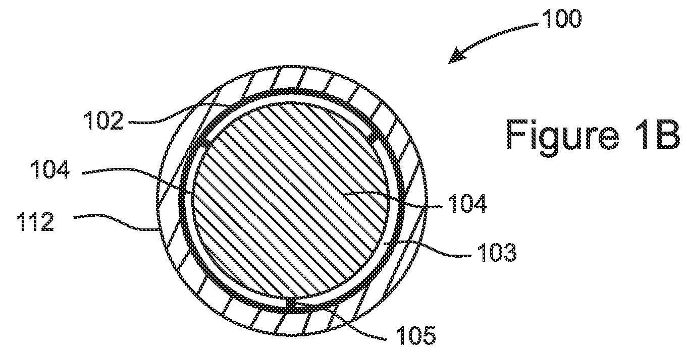
[0051]FIG. 2 illustrates a preferred embodiment 200 of the present invention that differs from the embodiment of FIG. 1A in that it has an overall U-shape, instead of the straight tubular shape 102 of FIG. 1A. However, the container 202 and heating element 204 contained therein are otherwise similar to the embodiment of FIG. 1A. The U-shaped configuration allows for a lengthier water passage 203 between the inlet 206 and the outlet 208 to be contained within a smaller space, thereby providing increased heat transfer to the fluid from the heating element 204 and a corresponding increase in the fluid heating rate. The U-shape of this embodiment also allows for shorter power conducting leads 210 that connect the heating element connectors 109, 111 to the power supply 212, since the two ends of the heating element 204 are positioned generally nearer to each other than in the case of a straight, tubular configuration such as is illustrated in FIG. 1A and FIG. 1B.

[0052]In the embodiment o...

embodiment 300

[0054]FIG. 3 illustrates another preferred embodiment 300 of the present invention that differs from the embodiments of FIG. 1A and FIG. 2 in that it has a general overall shape of a coil or spiral. However, the container 302 and the heating element contained therein 304 are otherwise similar to the embodiments of FIG. 1A and FIG. 2. The coil configuration of this embodiment 300 provides for a lengthier fluid passage 303 within a compact space, thereby increasing the heating capacity while occupying less space in the overall plumbing system. A power source 306 is connected by leads 307 to the heating element connectors 109, 111, which are located near each other, thereby minimizing the required lengths of the leads 307.

[0055]For simplicity of illustration, thermal insulation is not shown in FIG. 3 as surrounding the container 302. However, it will be understood that thermal insulation is included in some preferred embodiments that are otherwise identical to the embodiment of FIG. 3....


PUM


Abstract

A tankless electric water heater is disclosed that optimizes energy efficiency while minimizing cost and size. A flow-through container surrounds an electric heating element having a surface that is everwhere in direct, unobstructed relationship with the container walls, forming therebetween a passage through which all of the water must pass in a laminar flow while in close proximity to the heater surface, preferably within one-quarter inch and more preferably within one-eighth inch. The entire heater surface is surrounded by water, and all emanated heat must pass into the water. Tubular embodiments can be straight, coiled, U-shaped, and / or S-shaped. Cup-shaped embodiments can direct the water in a counter-flow past inner and outer heating element surfaces. Electrical connectors can be positioned near to each other. Protruding fins can be included that increase heat contact with the water, and the fins can be aligned with the water flow to minimize turbulence.

Description

FIELD OF THE INVENTION[0001]The invention generally relates to water heaters, and more specifically to tankless electric water heaters.BACKGROUND OF THE INVENTION[0002]Nearly all residential plumbing systems, as well as most commercial plumbing systems, include at least one water heater. Various types of water heater are available, depending on the size and type of plumbing system, on the expected patterns of usage, and on the local costs for various forms of energy.[0003]Many water heating systems include a water storage tank in which heated water is stored until use. Such “tank-based” water heaters are adaptable to almost any form of energy, including oil, gas, and electricity, and can provide high quantities of heated water on demand.[0004]However, tank-based water heaters suffer from several disadvantages. They are generally required to maintain large quantities of water at elevated temperatures for extended periods of time between use, and this wastes energy and money. Tank-bas...

Claims


Application Information

Patent Timeline
Patent Type & Authority Patents(United States)
IPC IPC(8): H05B3/78B67D7/80
CPCF24H1/142
Inventor HOLLIS, JEREMY LEE
Owner HOLLIS JEREMY LEE
Why Eureka
Try Eureka