Semiconductor device
a technology of semiconductor devices and dielectric tubes, which is applied in the direction of solid-state devices, amplifiers with semiconductor devices/discharge tubes, and basic electric elements, etc., can solve the problems of difficult to increase the resistance values of wirings, and achieve the effect of suppressing the damage of an integrated circuit due to esd
- Summary
- Abstract
- Description
- Claims
- Application Information
AI Technical Summary
Benefits of technology
Problems solved by technology
Method used
Image
Examples
embodiment 1
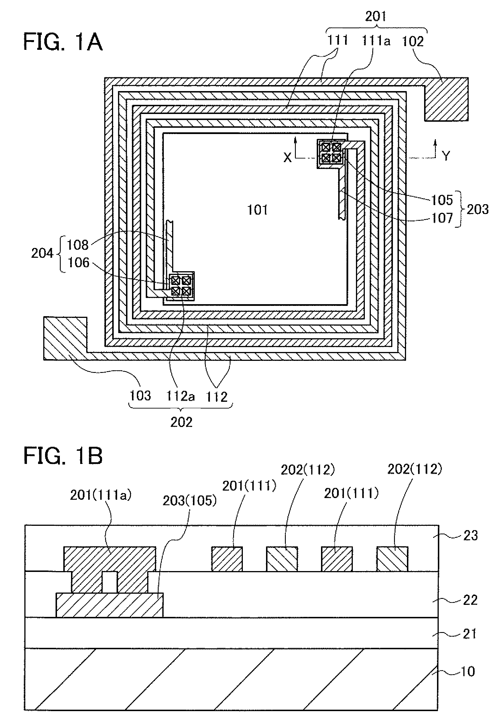
[0043]The structure of a semiconductor device of this embodiment is described with reference to FIG. 1A and FIG. 1B. FIG. 1A is a plan view illustrating the layout of the semiconductor device of this embodiment. FIG. 1B is a cross-sectional view taken along section line X-Y in FIG. 1A.
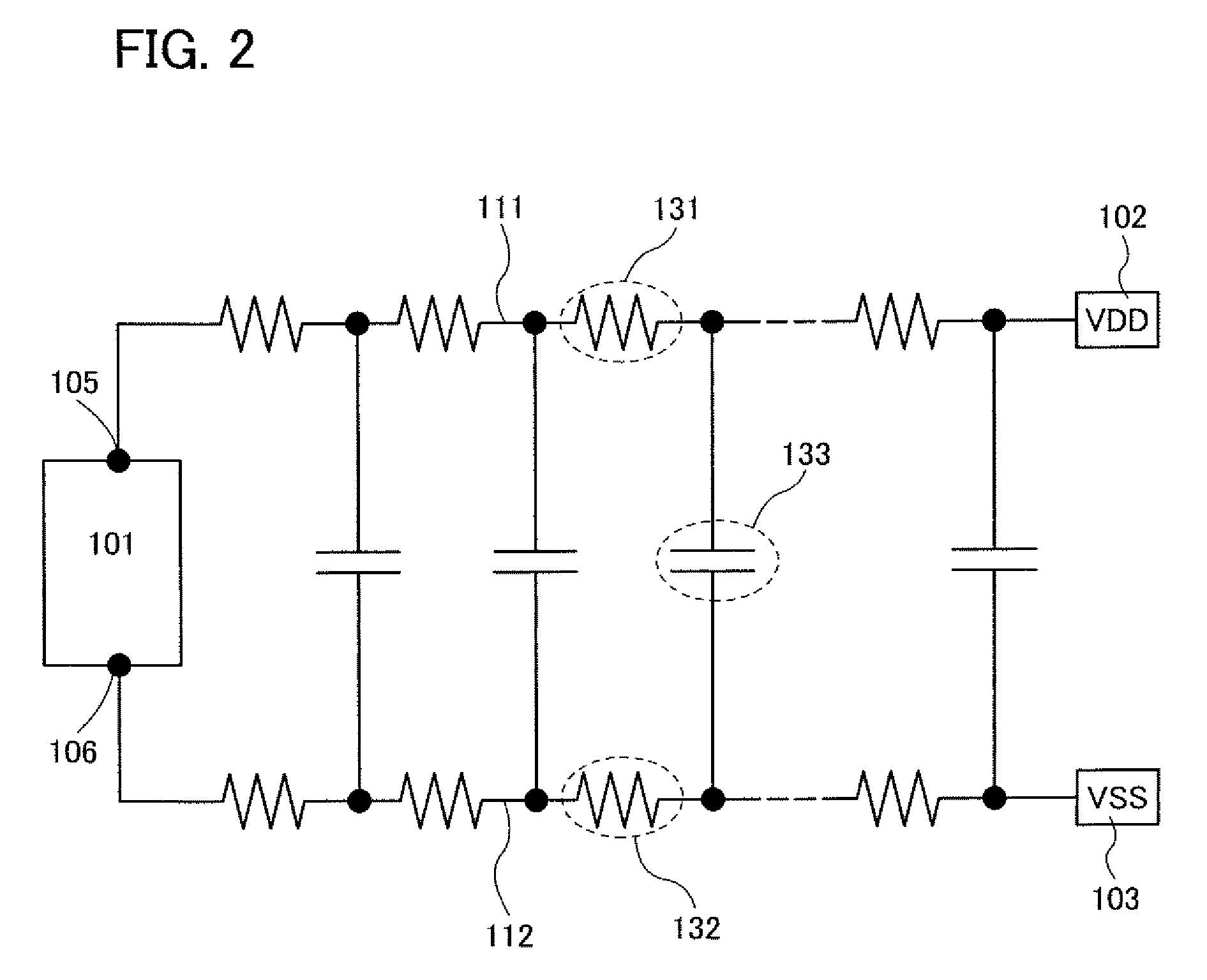
[0044]As illustrated in FIG. 1A, the semiconductor device includes an integrated circuit 101 having a plurality of semiconductor elements, a first terminal 102 to which a high power supply potential VDD is applied, a second terminal 103 to which a low power supply potential VSS is applied, a first wiring 111 which electrically connects the first terminal 102 and the integrated circuit 101 to each other, and a second wiring 112 which electrically connects the second terminal 103 and the integrated circuit 101 to each other.
[0045]The integrated circuit 101 includes a connection portion 105 electrically connected to the first wiring 111 a connection portion 106 electrically connected to the second wiring ...
embodiment 2
[0064]The structure of a semiconductor device of this embodiment is described with reference to FIG. 3A and FIG. 3B. FIG. 3A is a plan view illustrating the layout of the semiconductor device of this embodiment. FIG. 3B is a cross-sectional view taken along section line X-Y in FIG. 3A.
[0065]As illustrated in FIG. 3A, a semiconductor film 250 which overlaps with the first wiring 111 to which the power supply potential VDD is applied and the second wiring 112 to which the power supply potential VSS is applied is provided in the semiconductor device of this embodiment. The semiconductor film 250 is formed so as to surround the integrated circuit 101 in a manner similar to those of the conductive films 201 and 202. Here, the shape of the semiconductor film 250 is a quadrangle where an opening is formed in a portion overlapping with the integrated circuit 101.
[0066]As illustrated in FIG. 3B, the semiconductor film 250 is formed between the substrate 10 and the insulating film 21. The sem...
embodiment 3
[0072]In this embodiment, an example is illustrated in which each of the first wiring 111 and the second wiring 112 is formed using two conductive films which are stacked with an insulating film interposed therebetween. The structure of a semiconductor device of this embodiment is described with reference to FIG. 5A, FIG. 5B, FIG. 6A, and FIG. 6B. FIG. 5A is a plan view illustrating the layout of the semiconductor device of this embodiment. FIG. 5B is a cross-sectional view taken along section line X-Y in FIG. 5A. In addition, FIG. 6A and FIG. 6B are plan views each illustrating the layout of conductive films used for the first wiring 111 and the second wiring 112. FIG. 6A is a plan view of a second conductive film. FIG. 6B is a plan view of a first conductive film.
[0073]As illustrated in FIG. 5A, the first wiring 111 includes the conductive film 201 and the conductive film 203 which is used for the connection portion 105. In addition, the second wiring 112 includes the conductive f...
PUM
 Abstract
Description
Claims
Application Information
 - R&D
- Intellectual Property
- Life Sciences
- Materials
- Tech Scout
- Unparalleled Data Quality
- Higher Quality Content
- 60% Fewer Hallucinations
Browse by: Latest US Patents, China's latest patents, Technical Efficacy Thesaurus, Application Domain, Technology Topic, Popular Technical Reports.
© 2025 PatSnap. All rights reserved.Legal|Privacy policy|Modern Slavery Act Transparency Statement|Sitemap|About US| Contact US: help@patsnap.com


