
Integration of fluids and reagents into self-contained cartridges containing sensor elements

a technology of sensor elements and fluids, applied in the field of liquid analytes detection, can solve the problems of large and expensive instruments used in medical diagnostics, environmental monitoring, bioterrorism-related agents, etc., and achieve the effect of facilitating the digital/optical acquisition of fluorescent signals

Inactive Publication Date: 2012-01-31
BOARD OF RGT THE UNIV OF TEXAS SYST
View PDF338 Cites 88 Cited by
  • Summary
  • Abstract
  • Description
  • Claims
  • Application Information

AI Technical Summary

Benefits of technology

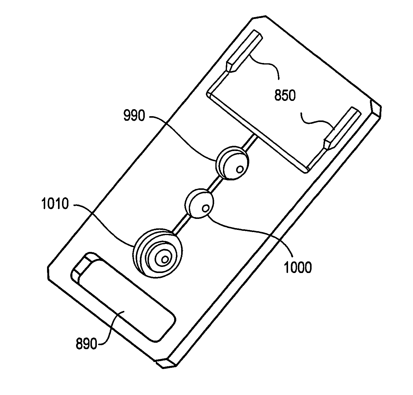
[0008]In an embodiment, a sample may be transported to a cartridge with the fluid delivery system. A sample may flow from the sample collection device to a sample reservoir in a cartridge. Reagents and / or buffers may be delivered to the sample reservoir. Reagents may be delivered by a reagent delivery system and / or contained in reagent reservoirs, reagent packs, and / or reagent pads. A sample reservoir may include a mixing chamber where a sample may react with reagents. An actuator coupled to the cartridge may drive fluid through the cartridge.
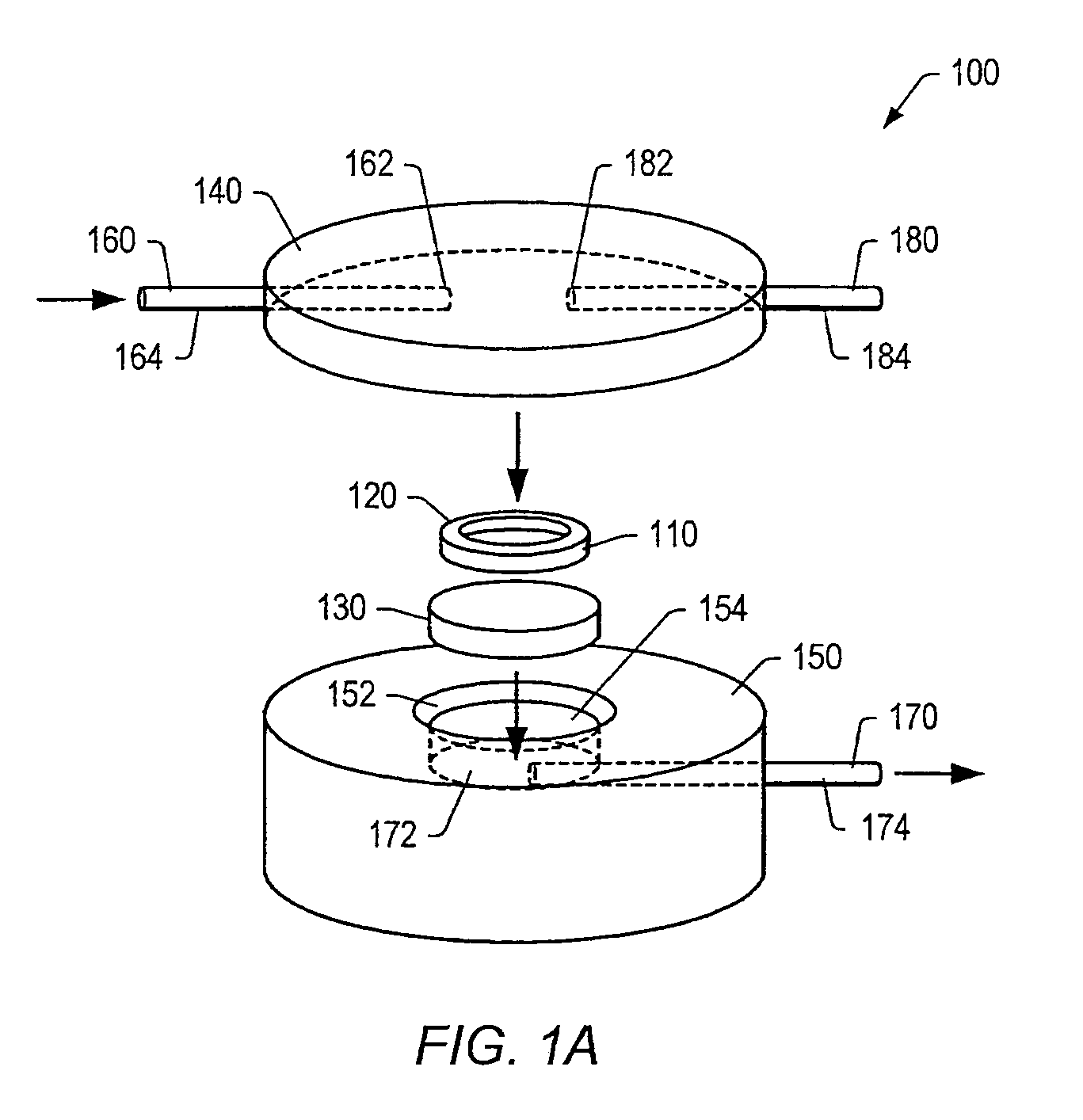
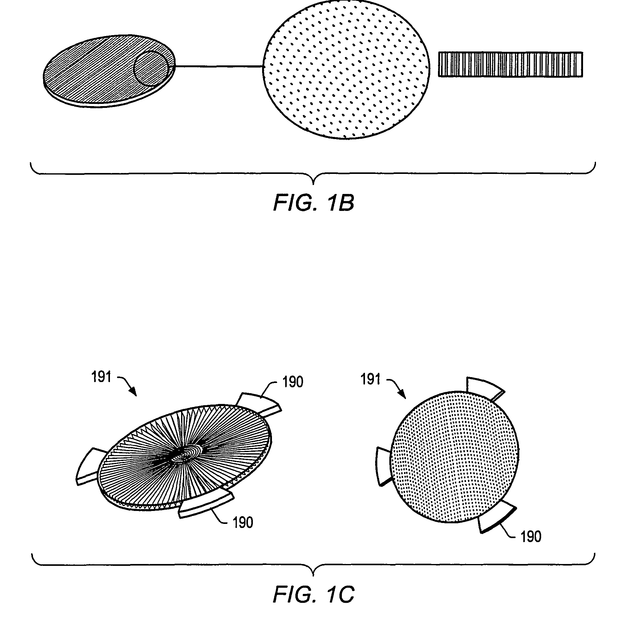
[0011]In one embodiment, populations of particles may be mechanically captured on the surface of a filter or membrane-equipped flow cell system. The membrane-equipped flow cell system may be configured to allow fluid flow through the flow cell system and the filter or membrane. In one embodiment, the membrane-equipped flow cell system may be coupled to an optical / digital acquisition system that may be configured to allow the visualization of particles captured thereon. In an embodiment, the membrane-equipped flow cell system coupled to an optical / digital acquisition system may comprise a device that may facilitate the digital / optical acquisition of fluorescent signals resulting from immunological reactions that take place on the surface of the membrane-captured particles.

Problems solved by technology

Current methodology used to complete medical diagnostics, environmental monitoring, and detection of bioterrorism-related agents often require large and expensive instruments and highly specialized personnel found only in certain hospitals, laboratories or government agencies.
Furthermore, these instruments are often restricted to a limited number of applications.
For example, in the area of medical diagnostics, each instrument is very specialized and designed either to measure protein levels or to analyze cellular matter but, typically, may never do both.
Additionally, each system is capable of analyzing only a few of the relevant markers of a disease, therefore adding another component to an already tedious and time consuming process that can vary from hours to days.
Long delays can be generated between the time of the initial visit, diagnosis, and administration of treatment, potentially having detrimental effects on the prognosis of the disease.

Method used


Image

  • Integration of fluids and reagents into self-contained cartridges containing sensor elements
  • Integration of fluids and reagents into self-contained cartridges containing sensor elements
  • Integration of fluids and reagents into self-contained cartridges containing sensor elements

Examples


example

[0201]Macroporous beads were prepared using the method for biphasic suspension polymerization method described herein. The beads so obtained were analyzed using light and fluorescence microscopy. The transparency of the agarose beads permitted the visualization of the fluorescent beads in different sections of the agarose beads. The presence of pores was confirmed by adding 1 μm fluorescent beads. Using light and fluorescence microscopy, the presence of conduits could not be conclusively determined. The beads accumulated into voids present in the bead, probably the ends of conduits.

[0202]Experiments were initially performed using Merck's Omnipure agarose powder. Low yields of non-spherical particles ranging between 250 and 300 μm were obtained. Experiments performed with an exaggerated amount of the hydrophilic emulsifier, 3.5 mL span 85 resulted in beads without pores but with a rough surface. By reducing the amount of the hydrophobic emulsifier, massive gellation due to the poor s...

examples

Materials

[0276]Polystyrene—polyethylene glycol (PS-PEG) graft copolymer microspheres (≈130 μm in diameter when dry and 230 μm when hydrated) were purchased from Novabiochem. Normal amine activation substitution levels for these particles were between 0.2 and 0.4 mmol / g. Commercial-grade reagents were purchased from Aldrich and used without further purification except as indicated below. Fluorescein isothiocyanate was purchased from Molecular Probes. All solvents were purchased from EM Science and those used for solid-phase synthesis were dried over molecular sieves. Methanol was distilled from magnesium turnings.

[0277]Immunoassays were performed using carbonyl diimidazole (CDI) activated Trisacryl® GF-2000 available from Pierce Chemical (Rockford, Ill.). The particle size for this support ranged between 40 and 80 μm. The reported CDI activation level was >50 μmoles / mL gel. Viral antigen and monoclonal antibody reagents were purchased from Biodesign International (Kennebunk, Me.). Rh...


PUM

PropertyMeasurementUnit
diameteraaaaaaaaaa
thicknessaaaaaaaaaa
diameteraaaaaaaaaa

Abstract

Described herein is an analyte detection device and method related to a portable instrument suitable for point-of-care analyses. In some embodiments, a portable instrument may include a disposable cartridge, an optical detector, a sample collection device and / or sample reservoir, reagent delivery systems, fluid delivery systems, one or more channels, and / or waste reservoirs. Use of a portable instrument may reduce the hazard to an operator by reducing an operator's contact with a sample for analysis. The device is capable of obtaining diagnostic information using cellular- and / or particle-based analyses and may be used in conjunction with membrane- and / or particle-based analysis cartridges. Analytes, including proteins and cells and / or microbes may be detected using the membrane and / or particle based analysis system.

Description

PRIORITY CLAIM[0001]This application claims priority to U.S. Provisional Application No. 60 / 548,613 entitled “PORTABLE INSTRUMENT FOR MICROARRAY ANALYSIS” filed on Feb. 27, 2004; U.S. Provisional Application No. 60 / 548,601 entitled “ON-CHIP COMBINATION OF CHEMICAL AND CELLULAR PANELS FOR ANALYSIS OF FLUID SAMPLES” filed on Feb. 27, 2004; and U.S. Provisional Application No. 60 / 548,190 entitled “CUSTOMIZED TESTING ENSEMBLES FOR COMPLEX FLUID ANALYSIS USING PORTABLE INTEGRATED MICROFLUIDICS / DETECTING UNITS” filed on Feb. 27, 2004.BACKGROUND[0002]1. Field of the Invention[0003]The present invention generally relates to a method and device for the detection of analytes in a fluid. More particularly, the invention relates to a portable apparatus for obtaining analytical information using both membrane- and particle-based detectors.[0004]2. Description of Related Art[0005]Current methodology used to complete medical diagnostics, environmental monitoring, and detection of bioterrorism-rela...

Claims


Application Information

Patent Timeline
Patent Type & Authority Patents(United States)
IPC IPC(8): G01N33/53B01L3/00G01N21/25G01N21/64G01N33/543
CPCB01L3/502715B01L3/502738G01N21/6428B01L2200/025B01L2200/027B01L2200/0605B01L2200/16B01L2300/0816B01L2300/0867B01L2300/0887B01L2400/0406B01L2400/0481B01L2400/0487B01L2400/0655Y10S436/809
Inventor MCDEVITT, JOHN T.BALLARD, KARRI L.FLORIANO, PIERRE N.CHRISTODOULIDES, NICK J.NEIKIRK, DEANANSLYN, ERICSHEAR, JASON
Owner BOARD OF RGT THE UNIV OF TEXAS SYST
Learn More