
Image projection system and method

a projection system and image technology, applied in the field of image projection system and method, can solve the problems of increasing complexity and cost, increasing the cost of the 3-slm system, and the die size is substantially limited, so as to reduce the width of the slm, the effect of efficient use of the di

Active Publication Date: 2012-01-31
KWON SUNG HOON
View PDF10 Cites 18 Cited by
  • Summary
  • Abstract
  • Description
  • Claims
  • Application Information

AI Technical Summary

Benefits of technology

[0030]An image projection system and method according to the present invention can efficiently use a die. More specifically, a Spatial Light Modulator (SLM) having a one-dimensional (1D) architecture may theoretically use a die corresponding to 1×1024 modulation devices, but has no choice but to use a die corresponding to, for example, 50×1024 modulation devices (in case where an aspect ratio is 1:20) because an actual die has a limited aspect ratio. Needless to say, even when the die corresponding to 50×1024 modulation devices is used, only 1×1024 modulation devices are formed in the SLM having the 1D architecture. However, an image projection architecture according to the present invention forms, for example, 2×512 modulation devices in one die, and thus only a 25×512 die can be used. Therefore, in comparison with conventional art, it is possible to efficiently use a die.
[0031]In addition, the projection system and method according to the present invention can reduce the width of an SLM while maintaining the same resolution of a screen. In other words, the projection system and method according to the present invention can increase the horizontal resolution of a screen while maintaining the same width of an SLM.
[0032]Additionally, the projection system and method according to the present invention can reduce the size of the system by decreasing a distance between an illumination optics and an SLM.
[0033]Further, the projection system and method according to the present invention do not generate shade between pixels of a screen.
[0034]Furthermore, the projection system and method according to the present invention, as shown in FIGS. 6, 7, and 8 (c), simultaneously emit the three primary colors and thereby obtain equivalent brightness efficiency to that which is available in a conventional 3-SLM system.
[0035]Still further, the projection system and method according to the present invention, as shown in FIG. 8 (c), can use a plurality of devices to modulate respective colors for each image pixel, and the respective modulation devices can operate at a many times lower rate.

Problems solved by technology

Since an SLM is the most expensive component in a projection system, the 3-SLM system is far more expensive than the single-SLM system.
In addition, the 3-SLM system requires an additional optics for accurately combining respective red, green and blue images, thus increasing its complexity and cost.
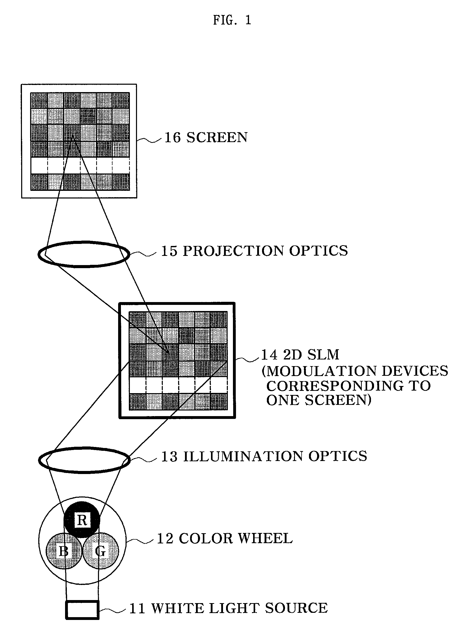
However, a die size is substantially limited for reasons relating to cutting, handling and packaging.
Conventional 2D SLMs have difficulty matching the core technology for a low-priced small projector.
It is difficult to miniaturize the 2D SLMs, and the reduction in pixel size leads to a very complicated and high priced production process.
Thus, a conventional SLM is too large and expensive to be incorporated into a low-priced small image projection system.
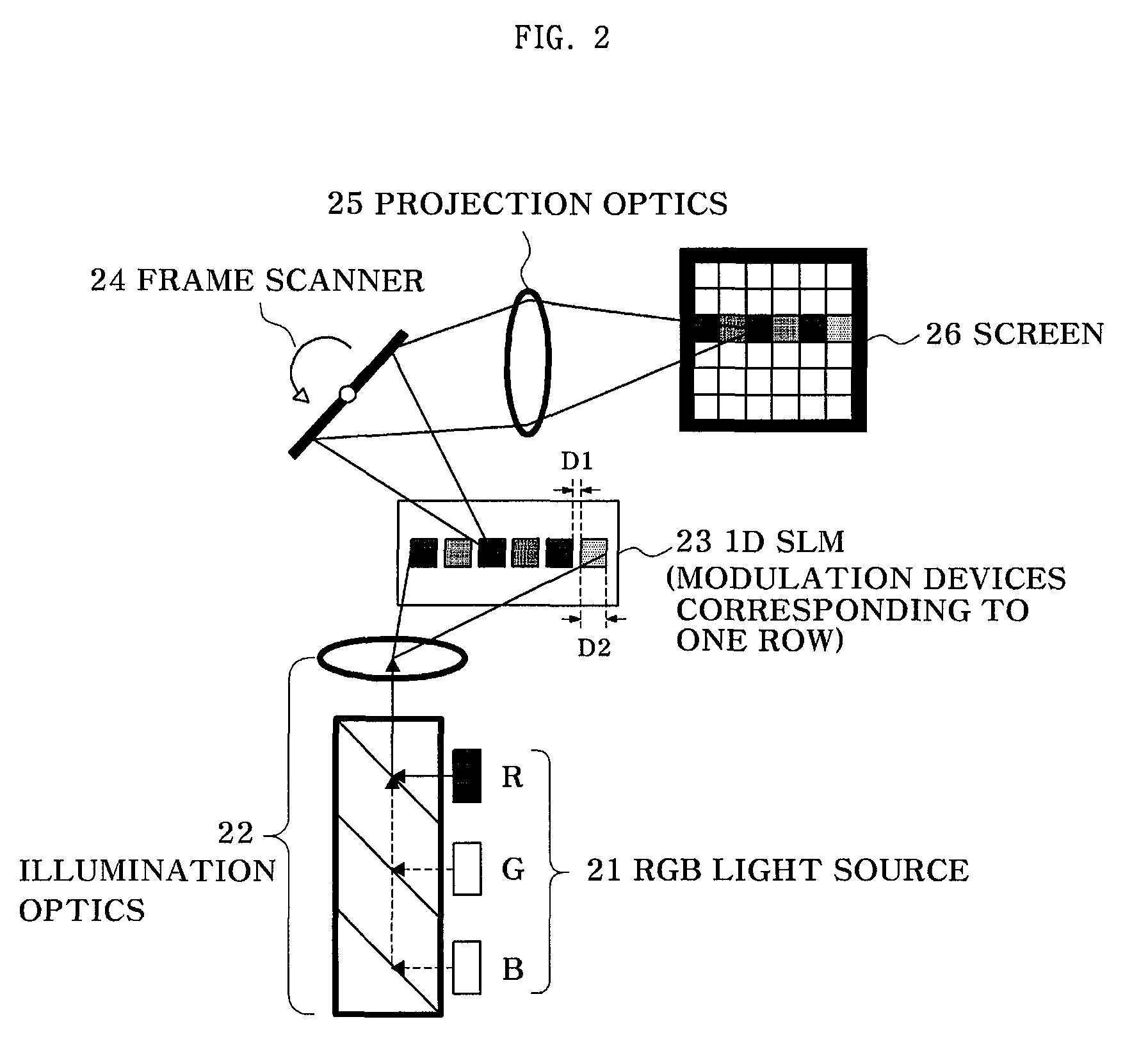
In addition, the 1D SLM according to conventional art has a disadvantage in that it still has the same width as a 2D SLM.
Furthermore, in the 1D SLM 23 according to conventional art, an interval D1 exists between modulation devices, and thus causes several problems.
This increases the production cost of the SLM and the size of an image projection system.

Method used


Image

  • Image projection system and method
  • Image projection system and method
  • Image projection system and method

Examples


Embodiment Construction

[0052]Hereinafter, exemplary embodiments of the present invention will be described in detail. However, the present invention is not limited to the exemplary embodiments disclosed below, but can be implemented in various ways. Therefore, the present exemplary embodiments are provided for complete disclosure of the present invention and to fully inform the scope of the present invention to those ordinarily skilled in the art.

[0053]FIG. 4 illustrates an image projection system according to a first exemplary embodiment of the present invention. Referring to FIG. 4, the projection system comprises a light source 31, an illumination optics 32, a Spatial Light Modulator (SLM) 33, a frame scanner 34, a projection optics 35, and a screen 36. The projection system may further comprise a coupling optics 37 and a color wheel 38.

[0054]The light source 31 performs a function of providing illumination light. The light source illustrated in FIG. 4 is a white light source. When the image projection...


PUM


Abstract

Provided are an image projection system and method, the image projection system including: a light source for providing illumination light; an illumination optics for receiving and illuminating the illumination light; a Spatial Light Modulator (SLM) having 2 rows of modulation devices formed to be offset from each other, each of the modulation devices modulating the light illuminated from the illumination optics; a frame scanner for scanning the modulated light from the SLM onto a screen to thereby generate a two-dimensional (2D) image corresponding to one frame on the screen; and a projection optics for projecting and focusing the modulated light transmitted from the frame scanner onto the screen.

Description

[0001]The present application claims priority to Korean Patent Application No. 10-2006-0072129 (filed on Jul. 31, 2006) and PCT International Patent Application No. PCT / KR2007 / 003335 (filed on Jul. 10, 2007) which are hereby incorporated by reference in its entirety.TECHNICAL FIELD[0002]The present invention relates to an image projection system and method, and more particularly, to a small-sized, low-priced and portable image projection system and method.BACKGROUND ART[0003]An increase in popularity and processing capability of mobile devices, such as laptop computers, cellular phones, Personal Digital Assistants (PDAs), digital cameras, Moving Picture Experts Group (MPEG) layer 3 (MP3) players, Personal Media Players (PMPs), etc., combined with an increase in high-speed wide area networks, has resulted in a large market for small-sized and low-priced image projection systems. Image projection systems can be used independently or installed in mobile devices. Like a mobile device, a...

Claims


Application Information

Patent Timeline
Patent Type & Authority Patents(United States)
IPC IPC(8): G03B21/14G03B21/00
CPCH04N9/3111H04N9/3114H04N9/3132H04N9/3173H04N9/3188H04N9/3197H04N5/74G02B26/10
Inventor KWON, SUNG-HOON
Owner KWON SUNG HOON
Learn More