Hollow fiber system

a technology of hollow fiber and fiber, applied in the field of hollow fiber arrangement, can solve the problem of constant pressure loss over the inflow area, and achieve the effect of uniform mass transfer

Active Publication Date: 2012-01-31
CARL FREUDENBERG KG
View PDF25 Cites 10 Cited by
  • Summary
  • Abstract
  • Description
  • Claims
  • Application Information

AI Technical Summary

Benefits of technology

[0006]In order to achieve the objective, the hollow fibers are spaced at least in part at a distance from each other by a device arranged between the hollow fibers. The device configured as a spacer prevents the fibers from clustering together locally due to the effect of the flow and prevents areas with a lower packing density from being formed. The pressure loss can be varied by various configurations of the device and can be specified over wide operating ranges. The hollow fibers can be arranged and secured by the device in such a way as to result in a constant pressure loss over the inflow area. This is particularly important in the case of asymmetrical inflows with which different dynamic pressures occur in the inflow area. In a first embodiment, the device can be in the form of a yarn whose diameter defines the distance between the fibers.
[0008]The device can comprise an open-cell foam. The open-cell foam can be in the form of a polyurethane foam. Foams are dimensionally stable, as a result of which the structure of the hollow fiber arrangement is stabilized. The foam entails a slight pressure loss.
[0009]The device can comprise a material that surrounds the hollow fibers like a spiral. For instance, the material can be a nonwoven or a foam. Since the device is configured here like a strip, material can be saved in comparison to a device configured with a full surface. The pressure loss with this arrangement is low since there are large interstices through which the stream can flow freely.
[0010]The device can be arranged in such a way that the hollow fibers can be separated into bundles. Here, a number of hollow fibers is encircled by the device, for instance, a yarn, thus forming individual chambers. This creates the possibility of a modular structure for the humidifier. The bundles can be individually replaced and can exhibit different properties, for instance, different diameters. Towards this end, hollow fibers having different diameters can be combined inside one bundle. Here, two hollow fibers of a smaller diameter can be combined with hollow fibers of a larger diameter. This configuration yields a stochastic, uniform distribution of hollow fibers having various diameters and accounts for a high porosity and a low pressure loss. In other embodiments, the bundles can contain different numbers of hollow fibers. This translates into bundles of different sizes and likewise results in a high porosity and a low pressure loss in an arrangement of the bundles.
[0014]The packing density of the hollow fibers can increase from the housing wall in the direction of the middle of the housing. As a result, the packing density is lowest in the inflow area of the hollow fiber arrangement and it increases in the direction of the middle of the housing. This translates into a uniform course of the pressure loss and a uniform mass transfer.
[0015]The housing can have an inlet opening through which the second air stream can be conducted to the hollow fibers and the hollow fibers can be arranged so as to be spaced at the smallest distance from each other in the area of the highest dynamic pressure and at the largest distance from each other in the area of the lowest dynamic pressure. In this context, the pressure loss is greatest in the area of the highest dynamic pressure and smallest in the area of the lowest dynamic pressure. This results in a uniform flow and thus in a uniform mass transfer over the cross section of the housing.

Problems solved by technology

The hollow fibers can be arranged and secured by the device in such a way as to result in a constant pressure loss over the inflow area.
In this case, the nonwovens are configured in such a permeable manner that they display a low pressure loss.

Method used


Image

  • Hollow fiber system
  • Hollow fiber system
  • Hollow fiber system

Examples


Embodiment Construction

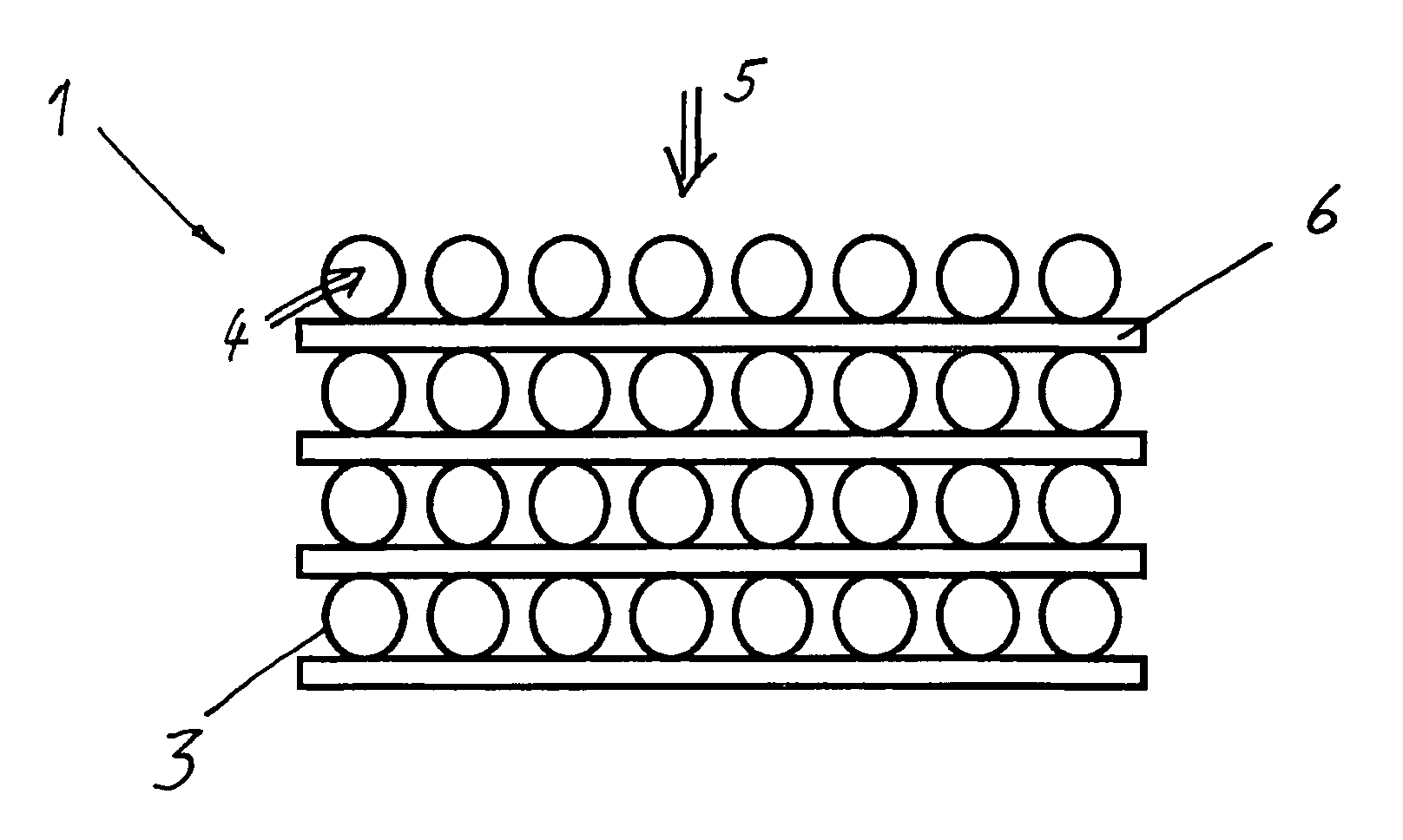
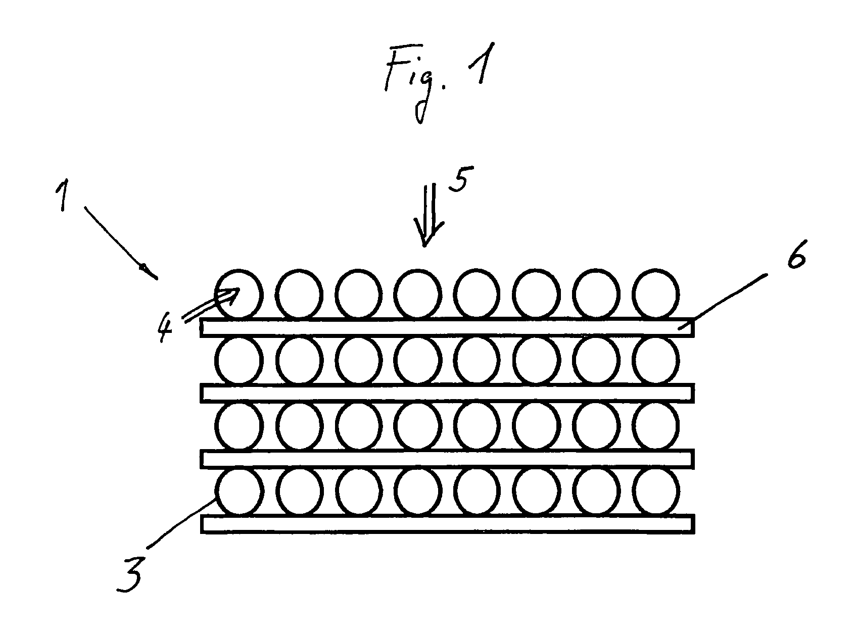
[0022]FIG. 1 shows a hollow fiber arrangement 1 that is particularly well-suited for a humidifier 2 of a fuel cell. The hollow fiber arrangement 1 is made up of hollow fibers 3 that are permeable to water-vapor, whereby a first air stream 4 can be conducted inside the hollow fibers 3 and a second air stream 5 can be conducted outside of the hollow fibers 3. The hollow fibers 3 are spaced at a distance from each other by a device 6. In this embodiment, the device 6 is in the form of a flat web of nonwoven material arranged perpendicular to the second air stream 5. The web of nonwoven material consists of synthetic fibers joined to each other in such a way that the forward resistance is low. In other embodiments, the device 6 can be also made of an open-cell foam, especially a polyurethane foam.

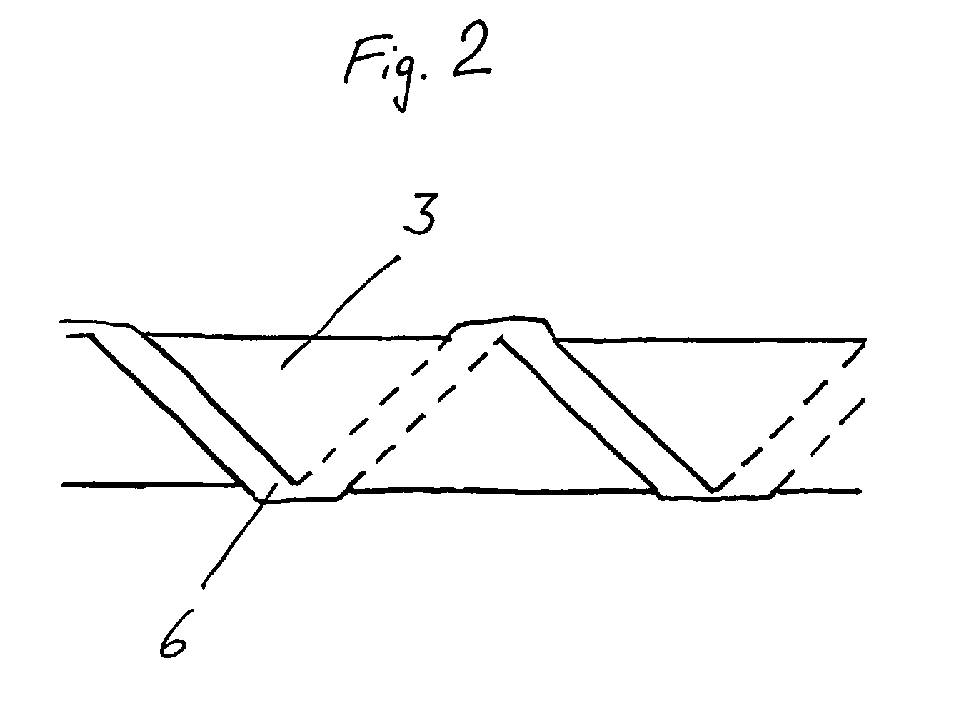
[0023]FIG. 2 shows a hollow fiber 3 that is surrounded like a spiral by the device 6. The device 6 consists of a narrow strip of nonwoven material.

[0024]FIG. 3 shows a hollow fiber arrangement ...


PUM

PropertyMeasurementUnit
distanceaaaaaaaaaa
packing densitiesaaaaaaaaaa
diametersaaaaaaaaaa

Abstract

Disclosed is a hollow fiber system for a humidifier, including hollow fibers that are permeable to steam. A first air flow can be conducted within the hollow fibers while a second air flow can be conducted outside the hollow fibers. The hollow fibers are located at least in part at a distance from each other via a device (6) that is disposed between the hollow fibers, respectively.

Description

[0001]This application is a national phase of International Application No. PCT / EP2006 / 004147, filed May 4, 2006, which claims priority to DE 10 2005 028 718.2, filed Jun. 20, 2005.FIELD OF THE INVENTION[0002]The invention relates to a hollow fiber arrangement for a humidifier, comprising hollow fibers that are permeable to water-vapor, whereby a first air stream can be conducted inside the hollow fibers and a second air stream can be conducted outside of the hollow fibers.BACKGROUND[0003]Such hollow fiber arrangements are generally known. The hollow fiber arrangements are disposed in humidifiers, whereby an air stream is conducted inside the fibers and another air stream is conducted outside of the fibers. In this context, one air stream is laden with water vapor that at least partially passes through the fibers into the other air stream. A problematic aspect of hollow fiber arrangements is that the air stream conducted on the outside causes the fibers to cluster together in some p...

Claims


Application Information

Patent Timeline
Patent Type & Authority Patents(United States)
IPC IPC(8): B01D53/22B01D63/04
CPCB01D53/22B01D63/02F24F6/043B01D2319/04B01D63/043B01D2313/14B01D2319/06
Inventor LEISTER, KLAUS
Owner CARL FREUDENBERG KG
Why Eureka
Try Eureka