
Sub-reflector of a dual-reflector antenna

a dual-reflector, sub-reflector technology, applied in the direction of antennas, electrical equipment, etc., can solve the problems of rf waves polluting the environment, the cost of shroud material, and the cost of assembly of the shroud on the primary reflector, so as to reduce the loss of spillover

Active Publication Date: 2012-01-24
RPX CORP
View PDF9 Cites 184 Cited by
  • Summary
  • Abstract
  • Description
  • Claims
  • Application Information

AI Technical Summary

Benefits of technology

The present invention proposes a dual-reflector antenna with reduced losses caused by spillover. The invention includes a sub-reflector with a unique contour ring that reduces multiple reflections and spillover losses. The invention also allows for a reduction in the height of the shroud, which results in cost and bulk advantages. The invention can be used in various applications such as terrestrial antennas and point-to-point radiofrequency links.

Problems solved by technology

These losses lead to a pollution of the environment by the RF waves.
Besides the congestion which results from it, this known solution exhibits the nowadays awkward drawback of the cost of the shroud material, as well as the cost of the assembly of this shroud on the primary reflector.

Method used


Image

  • Sub-reflector of a dual-reflector antenna
  • Sub-reflector of a dual-reflector antenna
  • Sub-reflector of a dual-reflector antenna

Examples


first embodiment

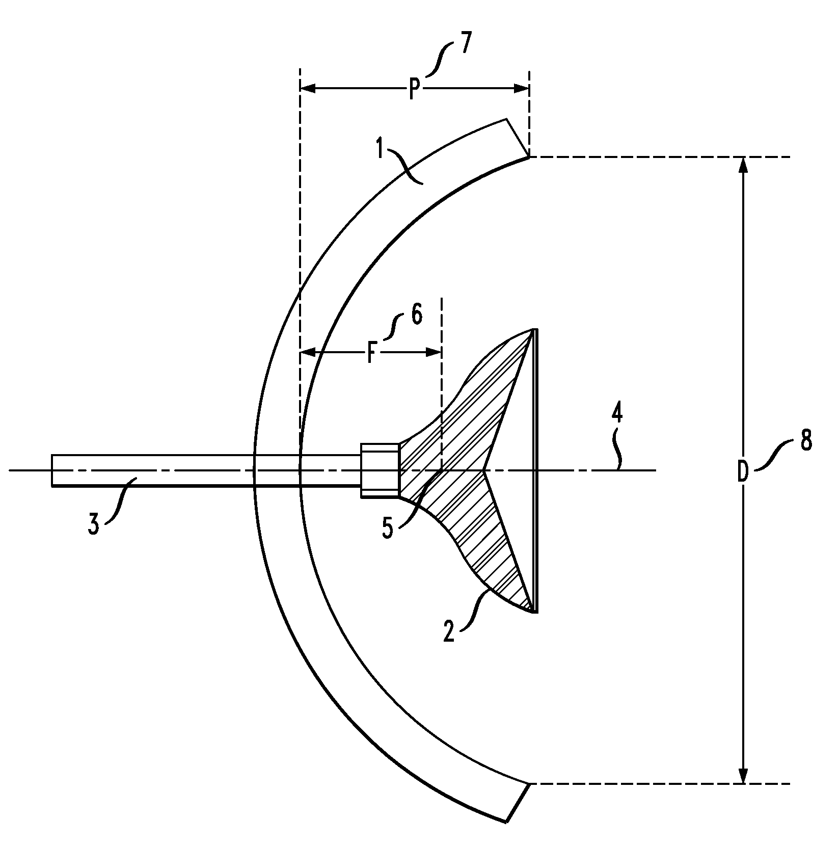
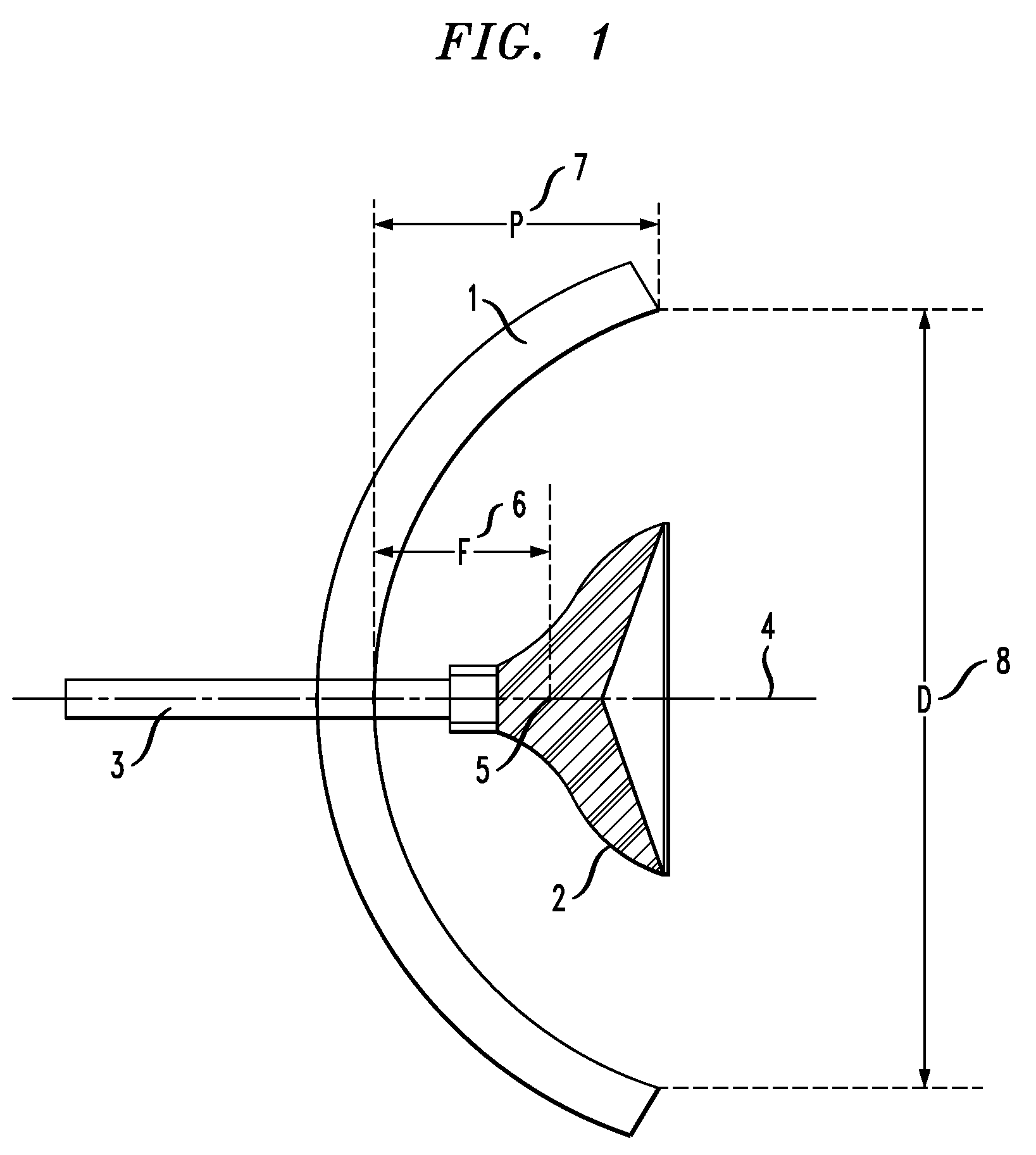
[0051]In FIG. 1, an RF antenna in accordance with the invention is represented in axial section. This antenna comprises an assembly made up of a concave primary reflector 1 and of a sub-reflector 2, as well as of a waveguide 3 serving moreover as support mechanism to the sub-reflector 2. The assembly exhibits a rotational symmetry around the axis 4.

[0052]The primary reflector 1 can be made of metal with a reflective surface, for example aluminum. The waveguide 3 can be for example a hollow metallic tube, also made of aluminum, of circular cross-section having an exterior diameter of 26 mm or 3.6 mm for frequencies of transmission / reception respectively of 7 GHz and 60 GHz. Of course the waveguide could have a different cross-section, rectangular or square for example.

[0053]One has represented the focal point 5 (also called phase center) placed on the axis of revolution 4, and the focal length F 6 which separates the focal point 5 from the vertex of the primary reflector 1. The prima...

second embodiment

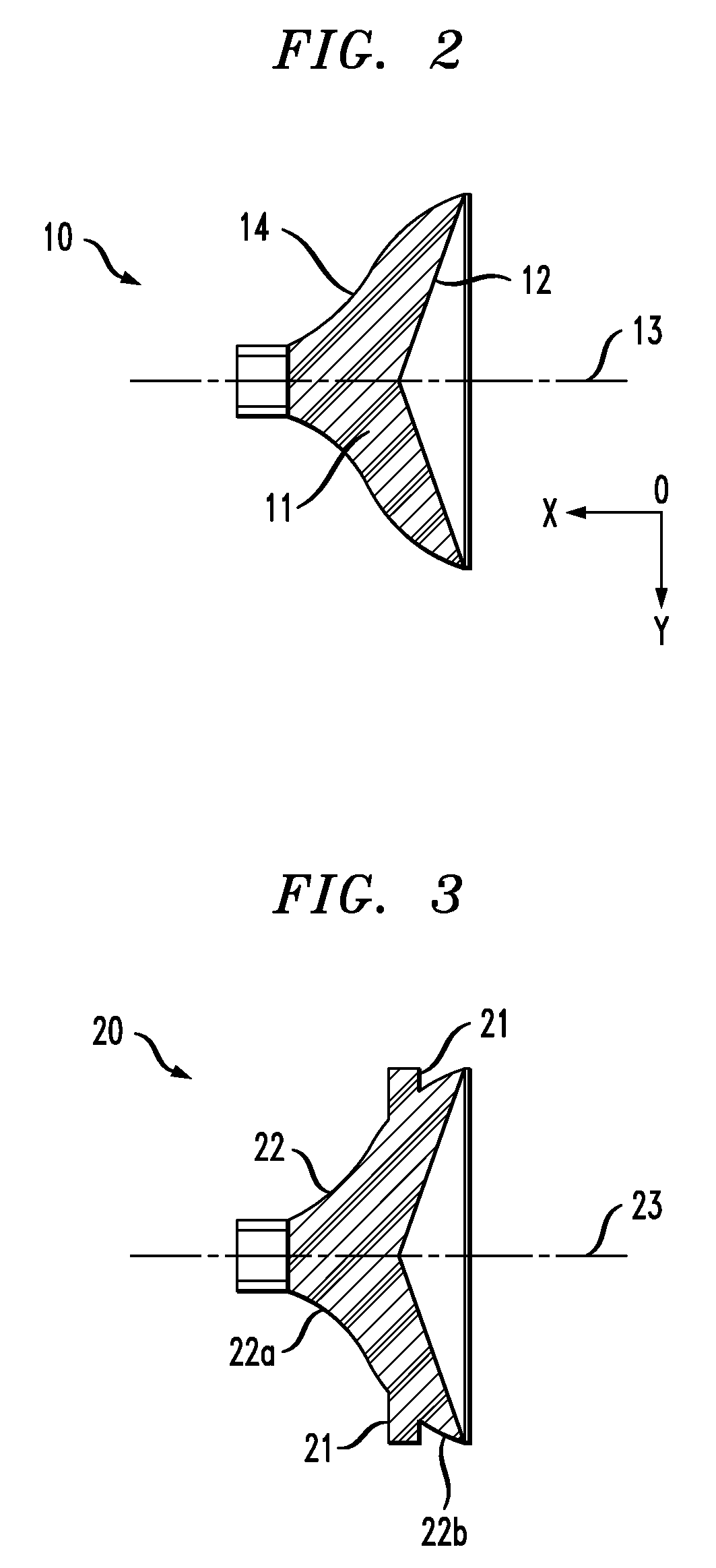
[0059]FIG. 3 represents the sub-reflector 20 of an antenna in accordance with the invention. A contour 21 forming a ring is arranged on the external surface 22 of the reflector 20. The profile of the external surface 22 on both sides of the contour 21 is a curve described by a polynomial equation of the sixth degree of the formula:

y=ax6+bx5+cx4+dx3+ex2+fx+g

[0060]In the second embodiment of the invention, the external surface 22 of the reflector 20 is thus made up of three successive parts 22a, 21, 22b. The parts 22a and 22b each exhibit a profile described by a portion of the curve of the sixth degree. The parts 22a and 22b and the contour 21 exhibit an axisymmetry around the axis of revolution 23.

[0061]The losses by spillover for transmission mode of an RF antenna in accordance with the first embodiment of the invention are clarified in FIG. 4. These losses correspond to the values of the angle of illumination 2θ of the primary reflector by the sub-reflector for which the RF waves ...


PUM


Abstract

The aim of the present invention is a sub-reflector of a dual-reflector antenna comprising:a first end having a junction of a first diameter, adapted for coupling to the end of a waveguide,a second end, having a second diameter greater than the first diameter,a convex reflective internal surface placed at the second end having an axis of revolution,an external surface of the same axis, joining the two ends,a dielectric material extending between the first and the second ends and limited by the internal surface and the external surface,In accordance with the invention, the external surface has a convex profile described by a polynomial equation of the sixth degree of the formula:y=ax6+bx5+cx4+dx3+ex2+fx+g where a is not zero.

Description

CROSS-REFERENCE TO RELATED APPLICATIONS[0001]This application is based on French Patent Application No 08 50 301 filed on Jan. 18, 2008, the disclosure of which is hereby incorporated by reference thereto in its entirety, and the priority of which is hereby claimed under 35 U.S.C. §119.BACKGROUND OF THE INVENTION[0002]The present invention relates to radio frequency (RF) dual-reflector antennas. These antennas comprise in general a concave primary reflector of great diameter exhibiting a surface of revolution, and a convex sub-reflector of lesser diameter situated in the vicinity of the focal point of the primary reflector. These antennas operate equally well in transmitter mode or in receiver mode, corresponding to two opposite directions of RF wave propagation. In the following, the description is given either in transmission mode or in reception mode of the antenna, according to whichever one better illustrates the described phenomena. It should be noted that all of the arguments...

Claims


Application Information

Patent Timeline
Patent Type & Authority Patents(United States)
IPC IPC(8): H01Q13/00
CPCH01Q19/193H01Q15/142H01Q19/134H01Q19/19
Inventor TUAU, DENISLE BAYON, ARMEL
Owner RPX CORP
Learn More