
Manually guided implement and method of producing a brake mechanism of a manually guided implement

a technology of manual guided implements and brake mechanisms, which is applied in the direction of manufacturing tools, braking elements, portable power-driven tools, etc., can solve the problem of relatively weak brake springs, and achieve the effect of low thermal stress of abrasion partners

Active Publication Date: 2012-01-24
ANDREAS STIHL AG & CO KG
View PDF9 Cites 1 Cited by
  • Summary
  • Abstract
  • Description
  • Claims
  • Application Information

AI Technical Summary

Benefits of technology

The present invention relates to a brake mechanism for a manually guided implement that includes a brake band and a brake drum that form abrasion partners that cooperate with each other during the braking process. The brake band is looped about the brake drum and includes a brake band that is embedded in a brake mechanism coating that contains diamond particles. The coating also contains nickel and phosphorous, which results in a tempering of the nickel matrix. The coating is applied using a nickel bath that disperses diamond particles. The use of the coating results in good braking performance with low wear and low roughness values. The thickness of the coating is low, and the coating is advantageously applied only to one of the abrasion partners, simplifying the manufacture of the other abrasion partner. The coating is chemically effected in a nickel bath, which allows for low layer thicknesses and maintains the increased strength of the brake band.

Problems solved by technology

As a result, the brake spring can be made relatively weak.

Method used


Image

  • Manually guided implement and method of producing a brake mechanism of a manually guided implement
  • Manually guided implement and method of producing a brake mechanism of a manually guided implement

Examples


Embodiment Construction

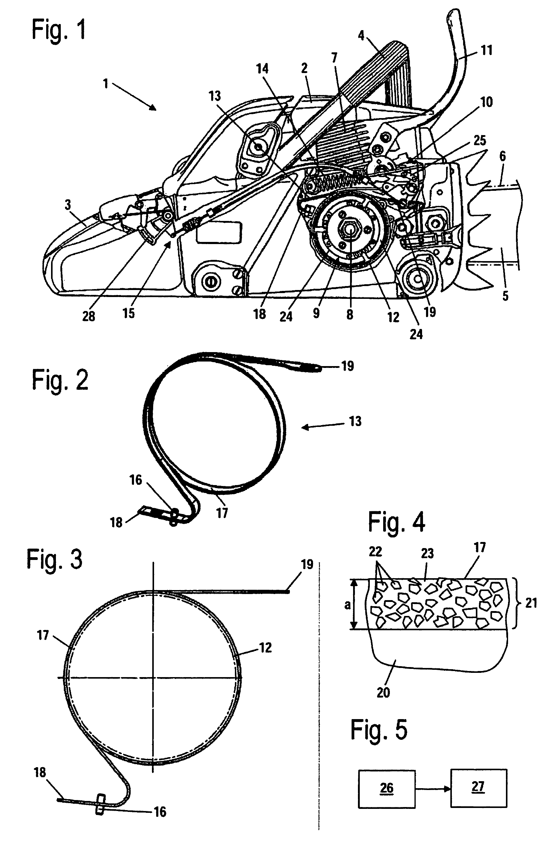
[0024]Referring now to the drawing in detail, the power saw 1 shown in FIG. 1 has a housing 2, in which are secured a rear handle 3 and a tubular handle 4 for guiding the power saw 1. The power saw has a guide bar 5 that extends toward the front from the front side, which is remote from the rear handle 3. A saw chain 6 circulates on the guide bar 5. The saw chain 6 is driven in a circulating manner by an internal combustion engine 7 that is disposed in the housing 2. An electric motor can also be provided instead of the internal combustion engine 7. The internal combustion engine is advantageously a two-cycle engine or a mixture-lubricated, four-cycle engine. The internal combustion engine 7 has a crankshaft 8, which is connected via a centrifugal clutch 9 with a pinion, which is not shown in FIG. 1, and which drives the saw chain 6.

[0025]The centrifugal clutch 9 has a brake drum 12, against which the centrifugal weights 24 of the centrifugal clutch 9 are pressed during operation du...


PUM


Abstract

A manually guided implement having a tool and a brake mechanism for the tool. The brake mechanism includes a brake band that is looped about a brake drum. The brake band and the brake drum form abrasion partners that cooperate with one another during a braking process. At least one of the abrasion partners has a coating. The coating is provided with diamond particles that are embedded in a matrix that contains nickel. The coating is effected in a nickel bath in which the diamond particles are dispersed.

Description

[0001]The instant application should be granted the priority date of May 24, 2007 the filing date of the corresponding German patent application DE 10 2007 024 170.6.BACKGROUND OF THE INVENTION[0002]The present invention relates to a manually guided implement having a tool and a brake mechanism for the tool, whereby the brake mechanism includes a brake band that is looped about a brake drum. The present invention also relates to a method of producing a brake mechanism of a manually guided implement.[0003]U.S. Pat. No. 4,949,818 discloses a brake band for the brake drum of a power saw, with the brake band being coated with a thermally applied friction layer.[0004]In particular with implements that have a safety brake and in addition a deceleration brake, the brake band is very highly stressed. This shortens the service life of the brake band.[0005]The brake band, the brake drum and the brake spring have a determinative effect upon the braking action. The brake spring exerts high forc...

Claims


Application Information

Patent Timeline
Patent Type & Authority Patents(United States)
IPC IPC(8): F16D49/08F16D69/02
CPCB25F5/00B27B17/083F16D49/02F16D65/065
Inventor STEHLE, HANS PETERSCHMIDT, VIKTORIA
Owner ANDREAS STIHL AG & CO KG
Learn More