
Liquid crystal display panel, liquid crystal display device having the same, and driving method thereof

a liquid crystal display and display panel technology, applied in static indicating devices, non-linear optics, instruments, etc., can solve the problems of disadvantageous increase in power consumption, achieve the effect of improving image quality, preventing or reducing the generation of afterimages and image flickering, and improving image quality

Active Publication Date: 2012-01-17
LG DISPLAY CO LTD
View PDF4 Cites 12 Cited by
  • Summary
  • Abstract
  • Description
  • Claims
  • Application Information

AI Technical Summary

Benefits of technology

The present invention provides a liquid crystal display panel, device, and method that improves image quality by preventing afterimages and flickering, and efficiently controls different kickback voltages. Additionally, the invention reduces power consumption. The technical effects of the invention include improved image quality, reduced power consumption, and improved control of different kickback voltages.

Problems solved by technology

Since the data voltage is raised to obtain the high brightness, power consumption is disadvantageously increased.

Method used


Image

  • Liquid crystal display panel, liquid crystal display device having the same, and driving method thereof
  • Liquid crystal display panel, liquid crystal display device having the same, and driving method thereof
  • Liquid crystal display panel, liquid crystal display device having the same, and driving method thereof

Examples


Embodiment Construction

[0038]Reference will now be made in detail to an embodiment of the present invention, an example of which is illustrated in the accompanying drawings.

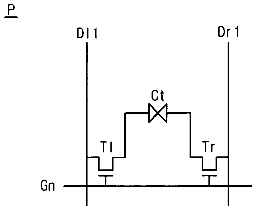
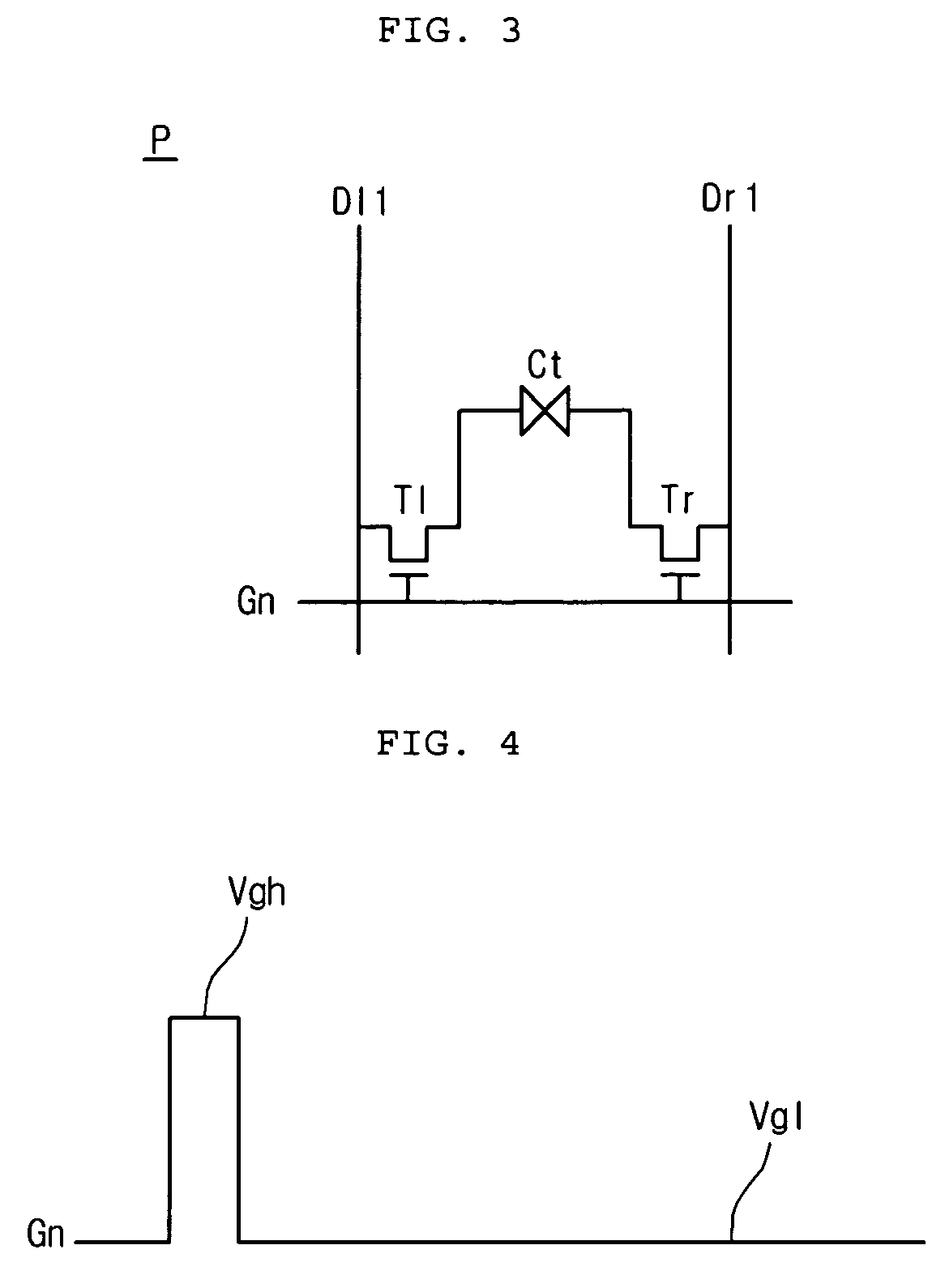
[0039]FIG. 3 is a schematic circuit diagram showing one pixel region according to the present invention.

[0040]Referring to FIG. 3, a pixel region P according to an embodiment of the present invention may be defined by one gate line Gn and first and second data lines Dl1 and Dr1. The pixel region P includes first and second thin film transistors T1 and Tr, and one liquid crystal cell Ct.

[0041]Gate electrodes of the first and second thin film transistors T1 and Tr are connected in common to the gate line Gn, and drain electrodes thereof are connected in common to the liquid crystal cell Ct, while source electrodes of the first and second thin film transistors T1 and Tr are connected to the first and second data lines Dl1 and Dr1, respectively.

[0042]The liquid crystal cell Ct includes a liquid crystal capacitance (Clc) formed by liquid cr...


PUM


Abstract

Provided is a liquid crystal display panel, a liquid crystal display device having the same, and a driving method thereof capable of improving image quality. The liquid crystal display device includes a liquid crystal display panel; a gate driver; and a data driver. The liquid crystal display panel includes pixel regions arranged in a matrix, each being defined by a gate line and first and second data lines crossing the gate line. The gate driver supplies a scan signal to the gate line. The data driver alternately supplies a data voltage and a common voltage to the first and second data lines.

Description

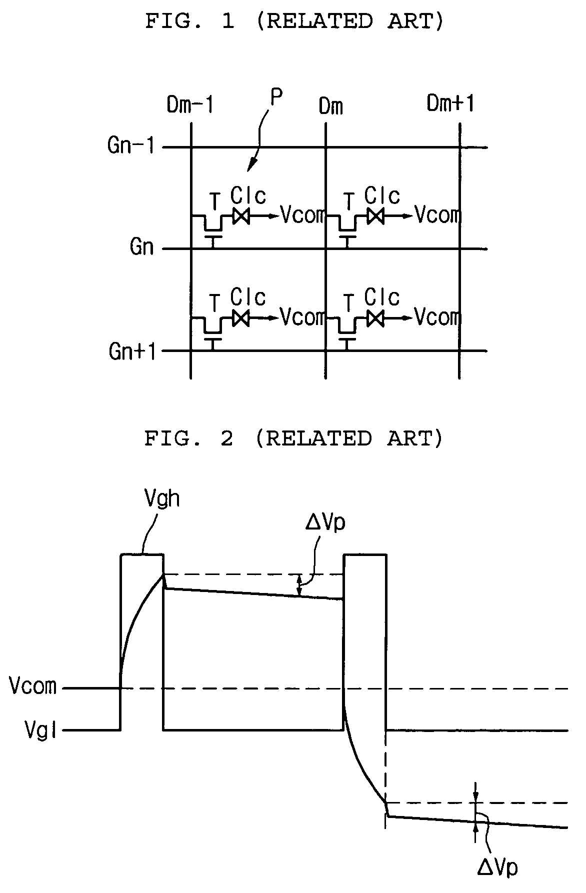
[0001]This application claims the benefit of Korean Patent Application No. 10-2006-0041733, filed on May 10, 2006, which is hereby incorporated by reference for all purposes as if fully set forth herein.BACKGROUND OF THE INVENTION[0002]1. Field of the Invention[0003]The present invention relates to a liquid crystal display device, and more particularly, to a liquid crystal display panel, a liquid crystal display device having the same, and a driving method thereof.[0004]2. Discussion of the Related Art[0005]A liquid crystal display (LCD) device displays an image by controlling light transmittance of liquid crystal cells according to an image signal. The LCD device may be driven using an inversion scheme in which data applied to a liquid crystal cell is periodically inverted to reduce image flickering and the generation of an after-image. The inversion schemes includes a line inversion scheme in which the polarity of data for a vertical line is periodically inverted, a column inversi...

Claims


Application Information

Patent Timeline
Patent Type & Authority Patents(United States)
IPC IPC(8): G09G3/36
CPCG02F1/13624G09G3/3614G09G3/3688G09G2300/0823G09G2310/027G09G2320/0257G02F1/133G09G3/36
Inventor KIM, CHEOL SE
Owner LG DISPLAY CO LTD
Learn More