Super-resolution optical recording medium

a super-resolution, optical recording technology, applied in the field of optical information recording, can solve the problems of destroying the information recorded and limiting the number of read cycles possible, and achieve the effect of convenient implementation

Inactive Publication Date: 2012-01-10
COMMISSARIAT A LENERGIE ATOMIQUE ET AUX ENERGIES ALTERNATIVES
View PDF11 Cites 0 Cited by
  • Summary
  • Abstract
  • Description
  • Claims
  • Application Information

AI Technical Summary

Benefits of technology

[0013]The invention provides a structure that is much simpler, easier to implement, which requires reasonable read laser power, and which may be subjected to numerous read cycles without substantial degradation of the read signal. The structure according to the invention relies directly on the non-linear properties of certain materials without which it would be necessary to subject them to a bubble expansion regime that is too difficult to control.
[0015]It has been observed that the presence of the ZnS / SiO2 layers around this antimonide layer makes it possible to considerably reduce the read laser power necessary to read the super-resolution information with a satisfactory signal / noise ratio. However, the question of the read power is critical as, on the one hand, a relatively high power is necessary to obtain a super-resolution effect via a localized change of the optical properties, but on the other hand, a high power tends gradually to destroy the information recorded, limiting the number of read cycles possible whereas as high a number of read cycles as possible is desired.

Problems solved by technology

However, the question of the read power is critical as, on the one hand, a relatively high power is necessary to obtain a super-resolution effect via a localized change of the optical properties, but on the other hand, a high power tends gradually to destroy the information recorded, limiting the number of read cycles possible whereas as high a number of read cycles as possible is desired.

Method used


Image

  • Super-resolution optical recording medium
  • Super-resolution optical recording medium

Examples


Embodiment Construction

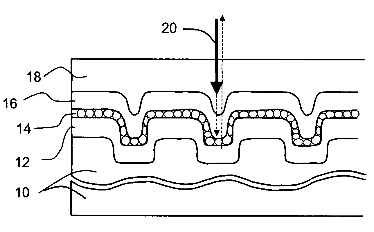
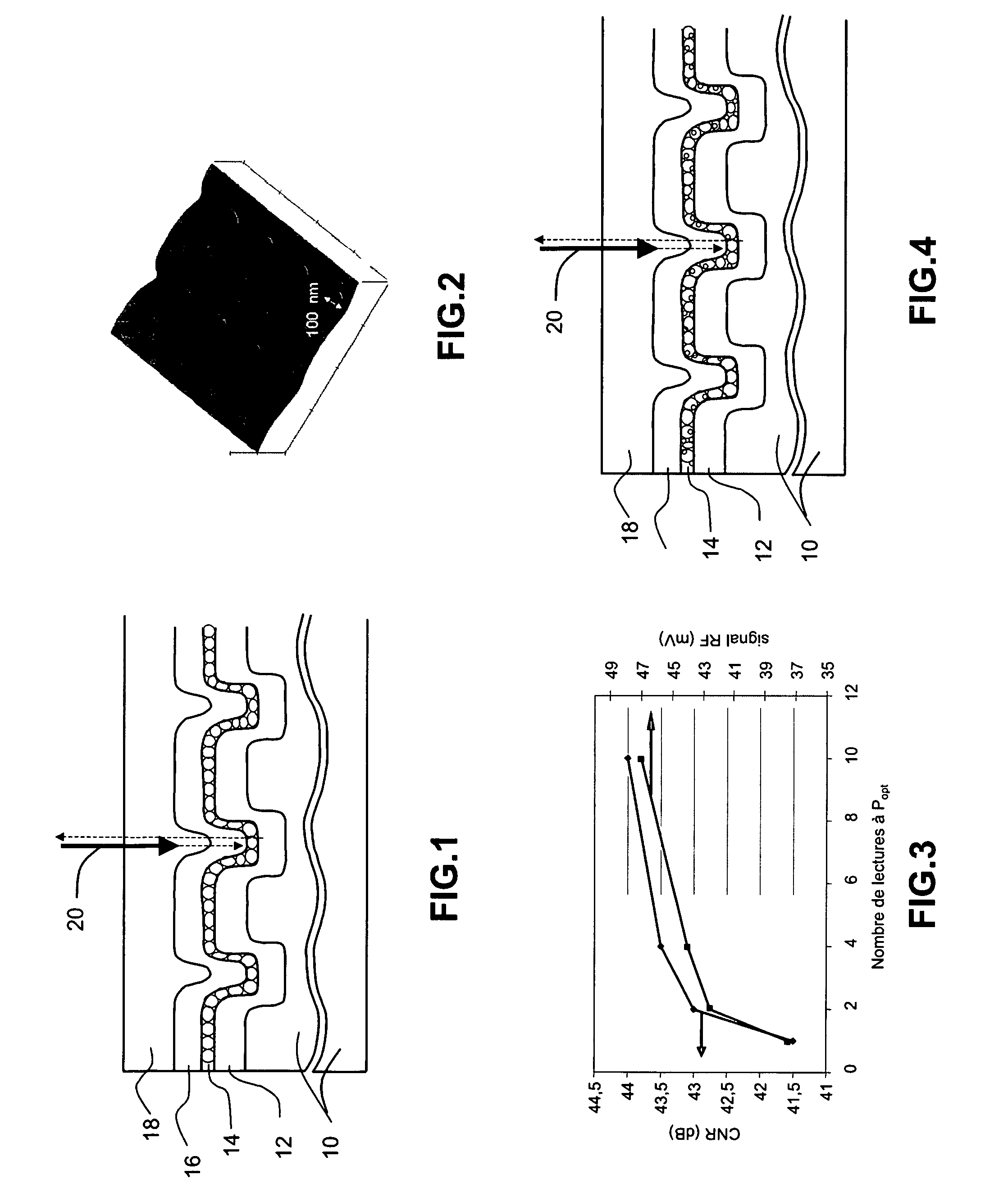
[0029]Represented in FIG. 1 is the general structure of the optical storage information medium according to the invention. It comprises a substrate 10, which is preferably an organic material, and notably polycarbonate conventionally used for optical disks. The substrate will, in practice, be in flat disk form and the information is conventionally written onto the disk along substantially concentric tracks; a read laser beam, symbolized by the arrow 20, placed in front of the disk will see the information pass in front of it during the rotation of the disk.

[0030]The substrate 10 comprises physical marks that define the information recorded, and in this example, the physical marks are constituted in the form of a relief imprinted into the upper surface of the substrate. The relief is, for example, composed of pits whose width is more or less fixed for all the information written, but whose length and spacing, in the run direction of the information define the content of the written i...


PUM

PropertyMeasurementUnit
average crystal grain sizeaaaaaaaaaa
grain sizeaaaaaaaaaa

Abstract

The invention relates to the field of optical information recording. According to the invention, an optical storage structure is proposed comprising a substrate equipped with physical marks whose geometrical configuration defines the recorded information, a superposition of three layers on top of the substrate marks, and a transparent protective layer on top of this superposition, the superposition comprising a layer of indium or gallium antimonide inserted between two ZnS / SiO2 dielectric layers. The antimonide layer has a polycrystalline structure with an average crystal grain size between 5 and 50 nanometers. The non-linear behavior of the superposition of three layers under the read laser makes it possible to read information having a size below the theoretical resolution of the reading system.

Description

RELATED APPLICATIONS[0001]The present application is based on, and claims priority from, French Application Number 07 02561, filed Apr. 6, 2007, the disclosure of which is hereby incorporated by reference herein in its entirety.FIELD OF THE INVENTION[0002]The invention relates to the field of optical information recording.BACKGROUND OF THE INVENTION[0003]When it is sought to increase the density of information recorded on an optical disk, this objective is generally limited by the performance of the information read device. The basic principle is that the physical information written to the disk can only be read with great difficulty when its size is smaller than the resolution limit of the optical system which will be used to read this information. Typically, when reading with a red laser having a wavelength of 650 nm and a numerical aperture of 0.6, there is normally no hope of correctly reading information having a size below 0.4 microns, or at the limit 0.3 microns.[0004]However...

Claims


Application Information

Patent Timeline
Patent Type & Authority Patents(United States)
IPC IPC(8): B32B3/02G11B7/257
CPCB82Y10/00B82Y20/00G11B7/257B82Y30/00Y10T428/21
Inventor HYOT, BERANGEREANDRE, BERNARDDESRE, PIERREBIQUARD, XAVIER
Owner COMMISSARIAT A LENERGIE ATOMIQUE ET AUX ENERGIES ALTERNATIVES
Why Eureka
Try Eureka