Cosmetic product applicator with multiple typically oriented elements
a technology of product applicators and typically oriented elements, applied in the field of cosmetic product applicators, can solve the problems of high cost of injection molding, long time required to launch such applicators, and many problems,
Inactive Publication Date: 2012-01-10
ALBEA SERVICES SAS
View PDF14 Cites 16 Cited by
- Summary
- Abstract
- Description
- Claims
- Application Information
AI Technical Summary
Benefits of technology
Enables the rapid production of a diverse range of applicators that can be adapted to different needs, reducing production costs and time, while maintaining high efficiency and flexibility in responding to market demands.
Problems solved by technology
Even though the applicators formed with a molded member of plastic material constitute an advantageous alternative to the use of traditional brushes, they however raise many problems.
Indeed:on the one hand, injection molding requires the very costly production of injection molds, which can only be justified if one is sure to be able to market large numbers of products,on the other hand, the time required to launch such applicators is very long, taking into account particularly the delay required for producing molds.
Method used
View moreImage
Smart ImageViewing Examples

Examples
examples
[0127]All the figures constitute examples of preferred embodiments.
[0128]Elements E 5 were molded with PE or PP, as well as with an elastomer.
Login to View More PUM
 Abstract
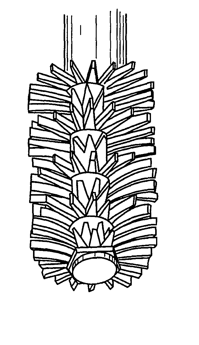
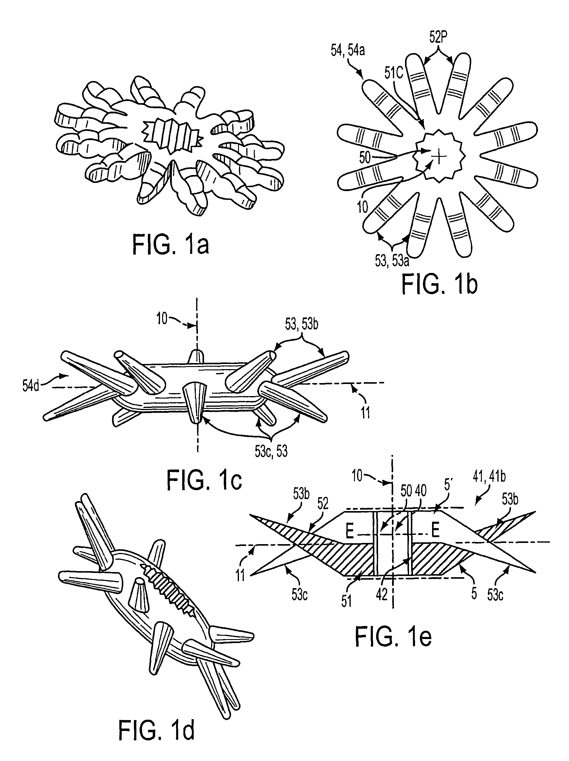
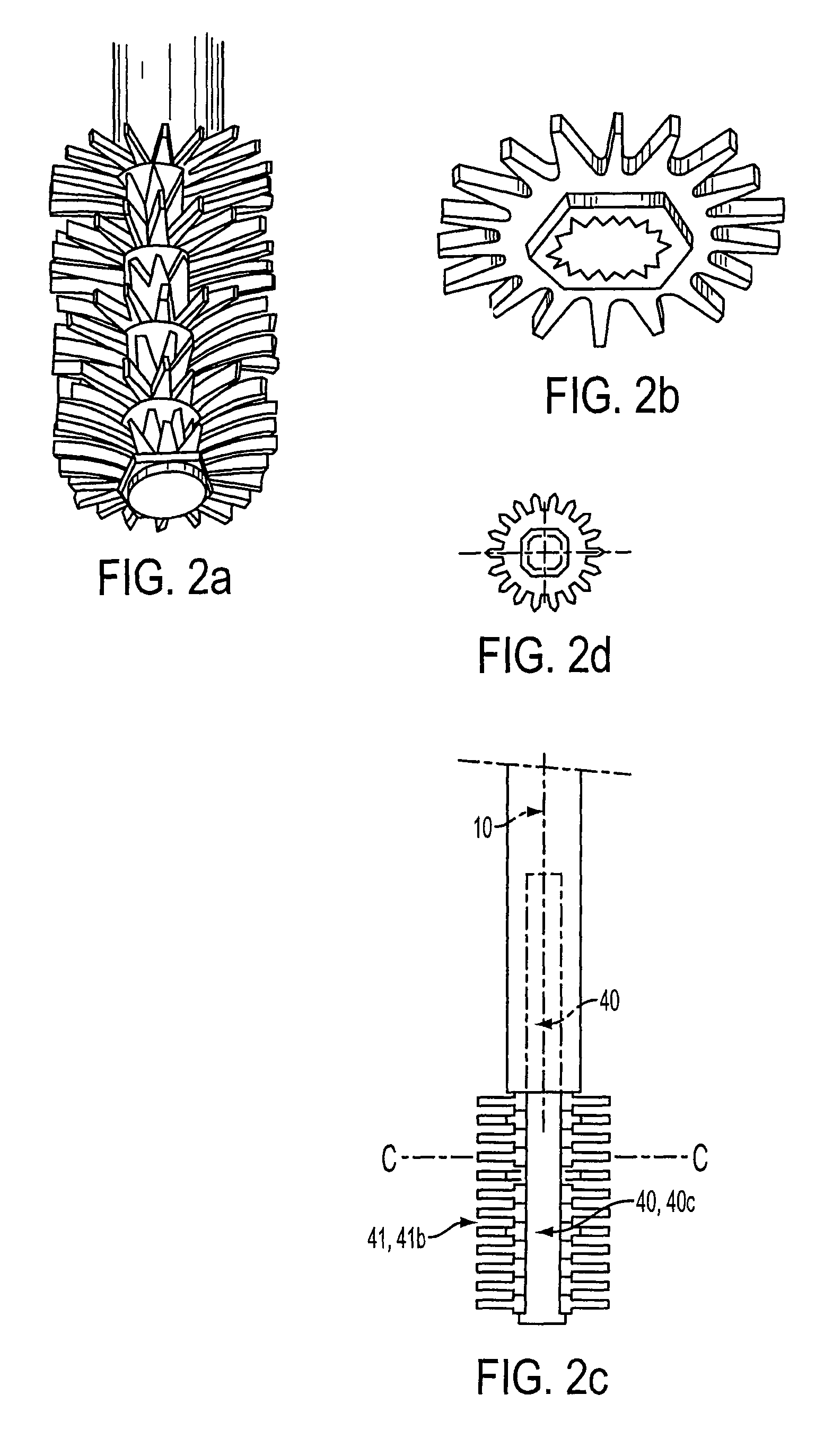
Applicator (1) for a cosmetic product, typically a mascara, comprising an application means (4) having an axial core (40) which is unitary with axial rod (3) at its lower part (31) and a stack (41) of a plurality of N elements which cooperate with axial core (40) through a typically central orifice (50) allowing the axial core (40) to extend therethrough, characterized in that: the elements are elements E (5) lacking complete rotation symmetry, and the axial core (40) and the plurality of elements E (5) operate jointly with an angular orientation means for elements E (5) with respect to axial direction (10), in a transverse plane (11) which is perpendicular to the axial direction (10), in a manner that each element Ei (5) is rotatably connected with axial core (40) and has a predetermined angular orientation αi with respect to the axial core (40).
Description
BACKGROUND OF THE INVENTION[0001](a) Field of the Invention[0002]The invention concerns the field of cosmetic product applicators, typically cosmetic products for eye make-up, such as for example mascaras.[0003](b) Description of Prior Art[0004]A great number of mascara applicators are already known.[0005]These applicators, which are intended to be used with a container defining a reservoir for the mascara, typically comprise:[0006]a) a cap adapted to seal said container and to be used as prehension means for said applicator,[0007]b) and axial rod,[0008]c) and a brush,[0009]said rod being unitary with said cap at one of its ends, and with said brush at its other end,[0010]said brush comprising a metallic twist to which a plurality of bristles are fixed.[0011]With respect to said brush, a very large number of embodiments of brushes are already known.[0012]Thus, the brushes described in the following French Patents are known: FR 2 505 633, FR 2 605 505, FR 2 607 372, FR 2 607 373, FR ...
Claims
Login to View More Application Information
Patent Timeline
 Patent Type & Authority Patents(United States)
IPC IPC(8): A45D40/26
CPCA45D40/262A46B9/021A45D40/265A46B2200/1053A46B2200/106
Inventor MANICI, DAVIDEBERHAULT, ALAIN
Owner ALBEA SERVICES SAS
Features
- R&D
- Intellectual Property
- Life Sciences
- Materials
- Tech Scout
- Unparalleled Data Quality
- Higher Quality Content
- 60% Fewer Hallucinations
Learn More Browse by: Latest US Patents, China's latest patents, Technical Efficacy Thesaurus, Application Domain, Technology Topic, Popular Technical Reports.
© 2025 PatSnap. All rights reserved.Legal|Privacy policy|Modern Slavery Act Transparency Statement|Sitemap|About US| Contact US: help@patsnap.com