
System and method for electronically discriminating a target

a target and electronic technology, applied in the field of fuzes, can solve the problems of high limited high-end munitions, and inability to accurately determine the type of targets, and achieve the effect of reducing the cost of conventional techniques

Inactive Publication Date: 2012-01-10
ARMY SEC OF THE U S GOVERNMENT AS REPRESENTED BY THE
View PDF1 Cites 15 Cited by
  • Summary
  • Abstract
  • Description
  • Claims
  • Application Information

AI Technical Summary

Benefits of technology

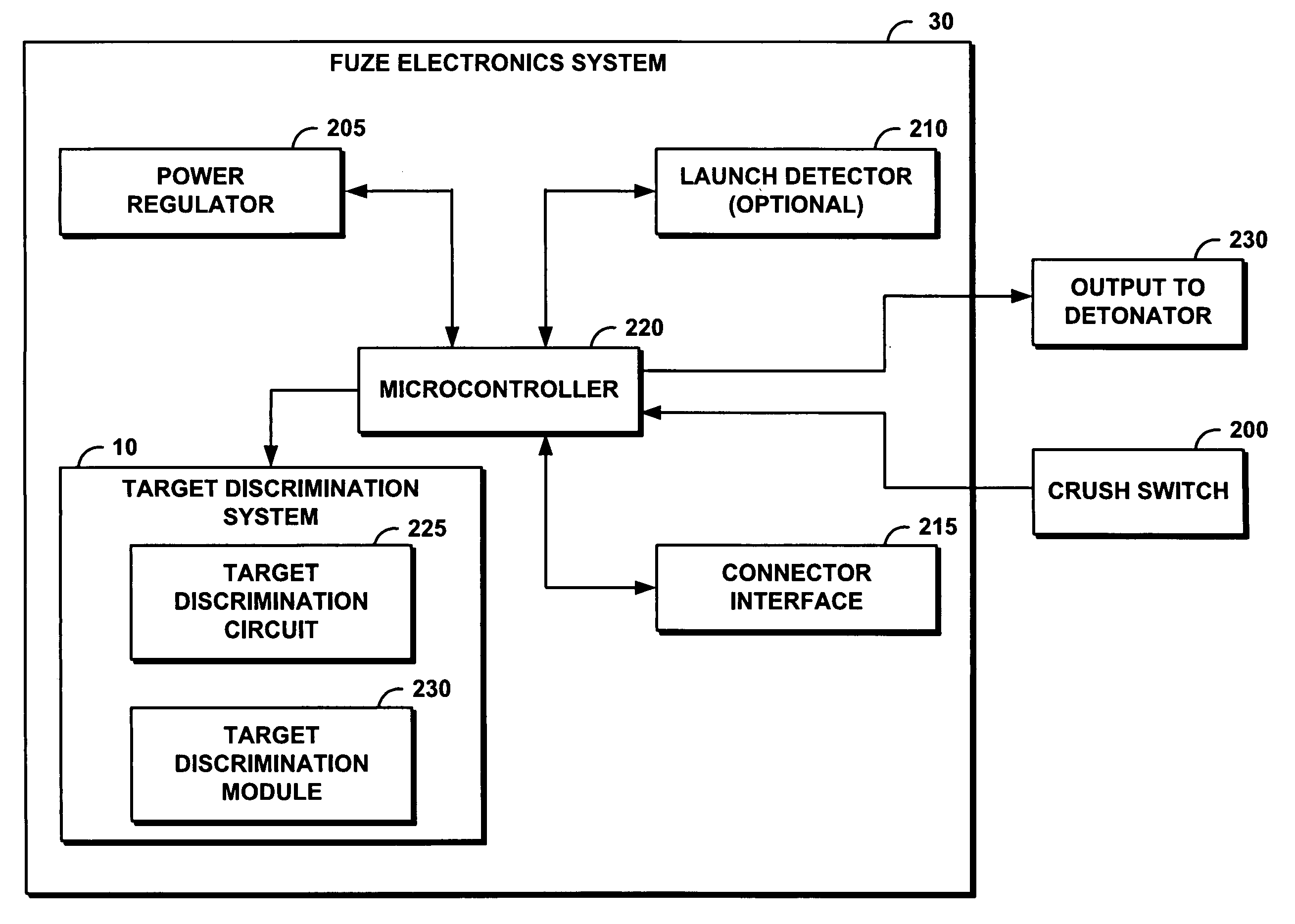
[0012]The target discrimination circuit comprises an acceleration switch that closes when a projectile impacts a target, enabling the system to detect a target impact. The target discrimination circuit further comprises a low-pass electronic filter to remove a high-resonant frequency from the acceleration switch signal generated at target impact. The target discrimination circuit comprises a comparator for comparing samples of the filtered acceleration switch signal with a reference voltage and generating a comparator data output of a value of approximately 5 volts which equates to digital logic one for each of the samples that exceeds the reference voltage and a value of approximately 0 volt or digital logic zero for each of the samples that falls below the reference voltage. The comparator data output is monitored by the target discrimination module to enable target discrimination.
[0013]In one embodiment, the acceleration switch comprises an omni-directional, normally open, spring mass acceleration switch. In another embodiment, the low-pass electronic filter comprises a 1 kHz low-pass electronic filter.

Problems solved by technology

The conventional technique for determining target type is, due to cost, currently limited to high-end munitions.
The high-cost of the conventional technique is primarily due to the cost of the one or more accelerometers used in target analysis and function mode determination.
The delay time is predetermined for optimal performance against earth and timber bunkers; however, this predetermined delay time is too long for targets such as a building.
In some cases, the munition may enter and exit the building before the warhead explodes, rendering the warhead ineffective.
The need for such a system has heretofore remained unsatisfied.

Method used


Image

  • System and method for electronically discriminating a target
  • System and method for electronically discriminating a target
  • System and method for electronically discriminating a target

Examples


Embodiment Construction

[0021]The following definitions and explanations provide background information pertaining to the technical field of the present invention, and are intended to facilitate the understanding of the present invention without limiting its scope:

[0022]Target Hardness: the resistance a target presents to a projectile. Targets are divided into two main categories, hard and soft. Soft targets are targets that allow the projectile to pass through without significantly deforming the warhead. Both thin walled structures, earth, and timber bunkers are considered soft targets. While both soft targets, a thick-walled target such as earth, timber, and timber bunker present a harder target than a building with thin walls such as plywood.

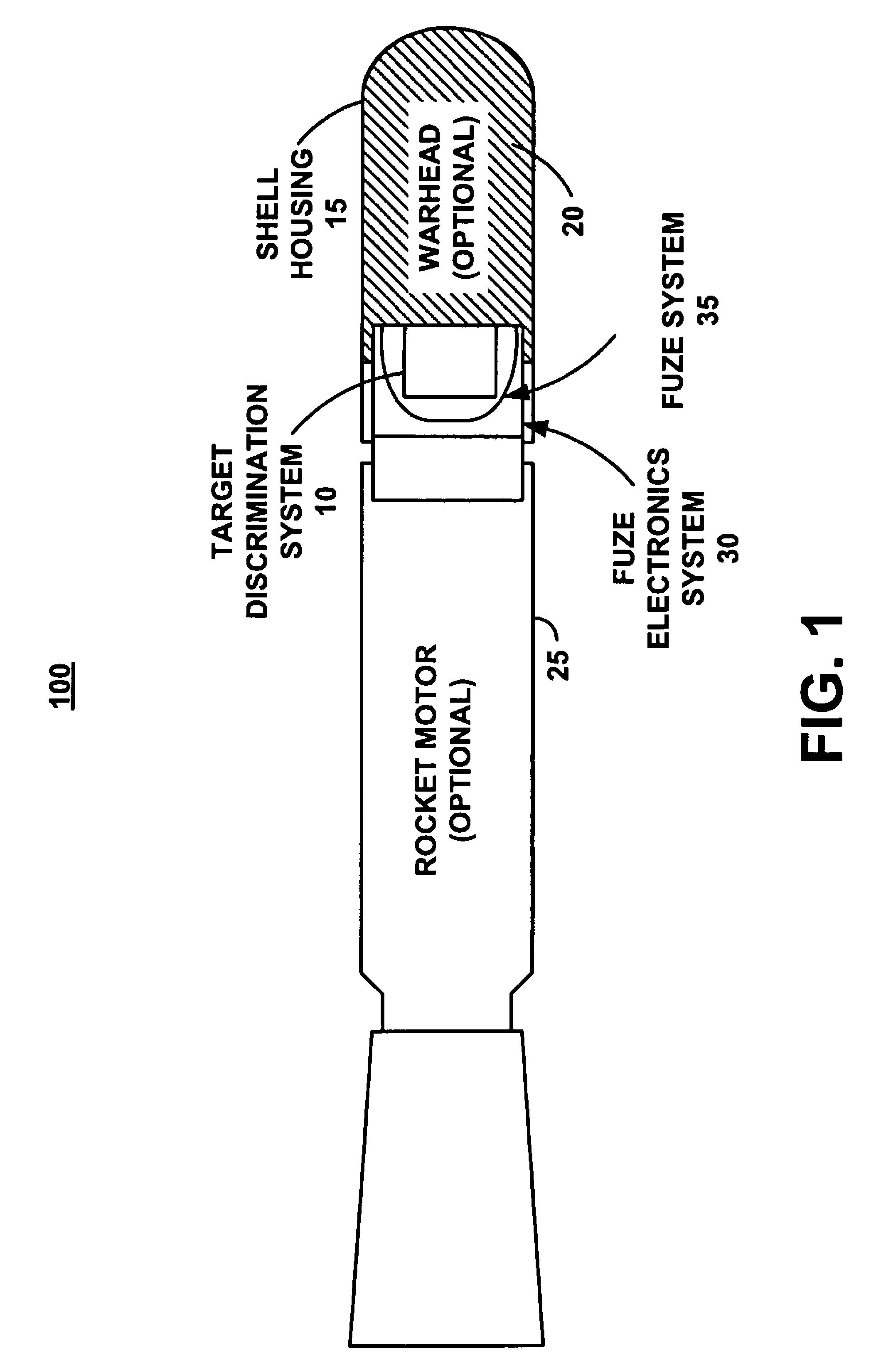
[0023]FIG. 1 illustrates a cross-sectional diagram of an exemplary projectile 100 in which a system, a computer product, an electronic product, and an associated method (the target discrimination system 10, or “system 10”) can be used. Projectile 100 further compris...


PUM


Abstract

A target discrimination system monitors an acceleration switch signal to determine an impact of a projectile on a target. During a sample period of approximately 1.0 milliseconds, the system repeatedly samples the acceleration switch signal, compares the sampled acceleration sensor signal with a reference voltage, and sets a comparator data output to logic one if the sampled signal exceeds the reference voltage. Otherwise, the comparator data output is set to logic zero. The system counts the instances that comparator data output equals logic one during the sample period and executes a selected delay. The selected delay is approximately 50 milliseconds if the counted number of instances exceeds a predetermined threshold of approximately two-thirds of the samples and, otherwise, the selected delay is approximately 10 milliseconds. The selective delay enables target discrimination and selective detonation of a projectile.

Description

PROVISIONAL APPLICATION[0001]The present application claims benefit under 35 USC 119(e) of provisional application Ser. No. 61 / 062,642, filed on Jan. 22, 2008, which is incorporated herein by reference.U.S. GOVERNMENTAL INTEREST[0002]The inventions described herein may be manufactured, used and licensed by or for the U.S. Government for U.S. Government purposes.FIELD OF THE INVENTION[0003]The present invention generally relates to a fuze for munitions such as explosive projectiles. More particularly, the present invention relates to using a discriminating timing device to arm and detonate a fuze for an explosive projectile based on detection by the explosive projectile of the target hardness; i.e., the thickness of a wall through which the explosive projectile passes to reach the target at which detonation is desired.BACKGROUND OF THE INVENTION[0004]Munitions are getting smarter in guidance and in target detection. Conventional high-end munitions currently utilize electronics to det...

Claims


Application Information

Patent Timeline
Patent Type & Authority Patents(United States)
IPC IPC(8): F42D3/00
CPCF42C9/147
Inventor KHUC, LLOYD D.SCHWARTZ, BARRY
Owner ARMY SEC OF THE U S GOVERNMENT AS REPRESENTED BY THE
Learn More