RF coil and MRI system
a technology of rf coils and mri, applied in the field of rf coils, can solve the problems of complex adjustment, increased manufacturing costs, and decreased orthogonality, and achieve the effects of easy adjustment of the transceiver system, reduced manufacturing costs, and high signal-to-noise ratio
- Summary
- Abstract
- Description
- Claims
- Application Information
AI Technical Summary
Benefits of technology
Problems solved by technology
Method used
Image
Examples
first embodiment
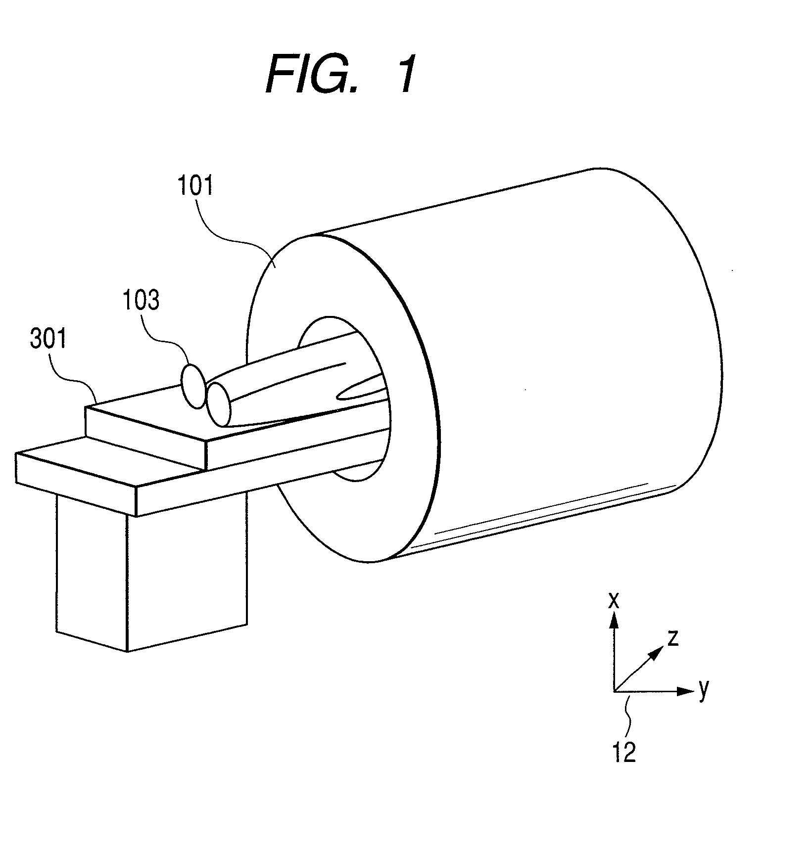
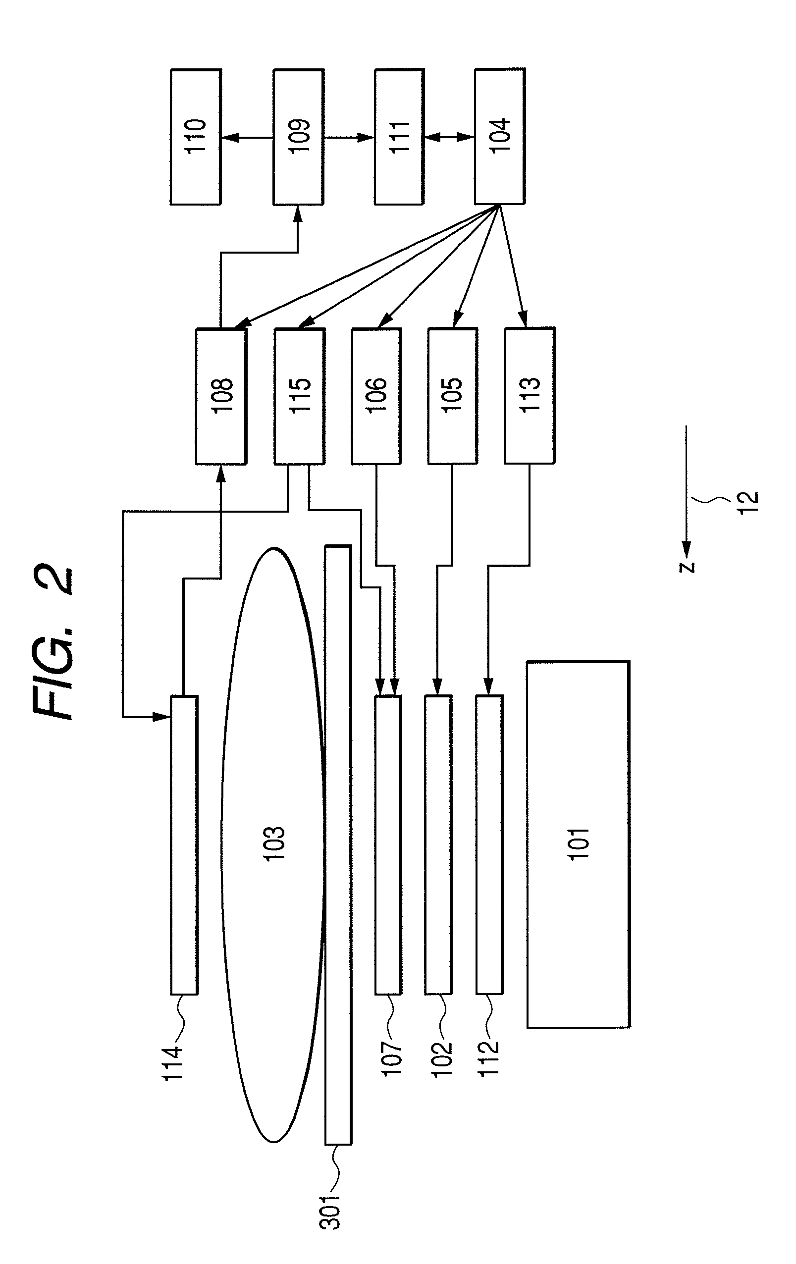
[0056]A magnetic resonance imaging apparatus according to the first embodiment will now be described. FIG. 2 is a block diagram showing the main features of the construction. Identical elements to those in FIG. 1 are denoted by identical symbols. The magnetic resonance imaging apparatus shown in the diagram includes the magnet 101, a gradient coil 102, a shim coil 112 for adjusting the uniformity of the static magnetic field, a sequencer 104 which controls the field application sequence, a transmit RF coil 107 which generates a RF magnetic field, and a receive RF coil 114 which detects a magnetic resonance signal. The gradient coil 102 and shim coil 112 are connected to a gradient coil power supply 105 and shim coil power supply 113, respectively. The transmit RF coil 107 is connected to a RF magnetic field generator 106 and magnetic decoupling driver 115, and the receive RF coil 114 is connected to a receiver 108 and the magnetic decoupling driver 115. The transmit RF coil 107 and ...
second embodiment
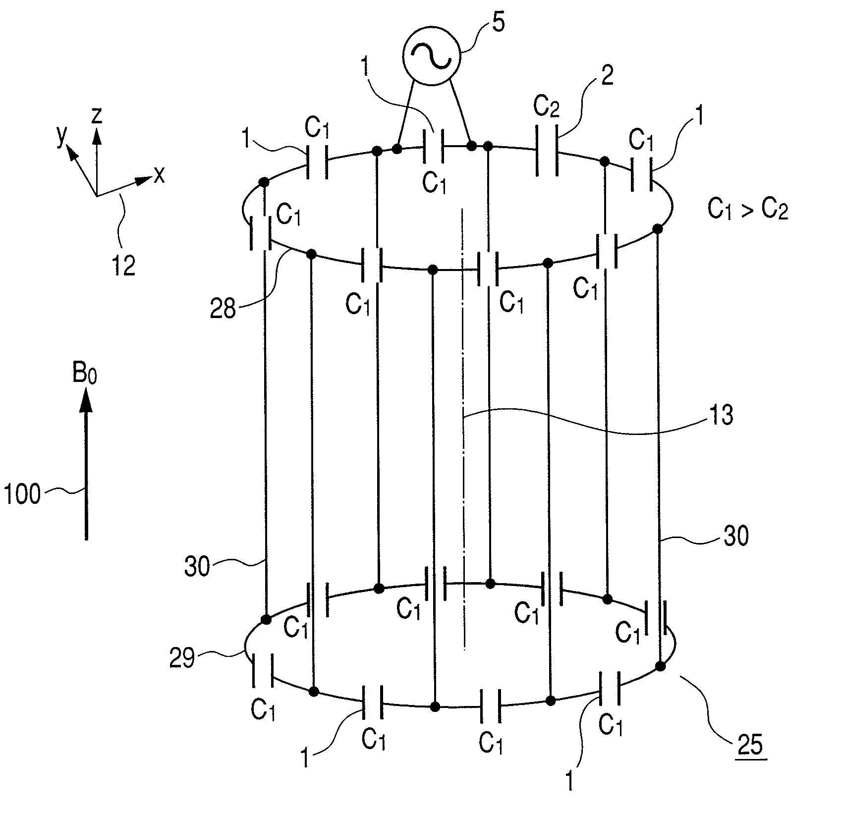
[0119]FIG. 23 shows the construction of a birdcage-type circularly-polarized RF coil 25 according to a second embodiment of the invention. In the birdcage-type circularly-polarized RF coil 25, as shown in FIG. 23A, the 2 loop conductors 28, 29 are disposed so that the center axes of the loops are parallel and substantially parallel to the z axis of the axes 12, and plural (in FIG. 23A, 8) linear conductors 30 which are substantially linear and substantially parallel to the z axis of the axes 12, are connected thereto. At this time, the plural linear conductors 30 are disposed at equidistant intervals. It is assumed that the direction of the z axis of the axes 12 is identical to the orientation of the static magnetic field 100 generated by the magnet 101 of the magnetic resonance imaging apparatus. In other words, the central axis of the loops is substantially identical to the orientation of the static magnetic field generated by the magnet of the magnetic resonance imaging apparatus...
third embodiment
[0150]A TEM-type circularly-polarized RF coil 31 which is a third embodiment of this invention, will now be described. This RF coil may also be used as a transmit or receive RF coil. FIG. 30 is a diagram showing the construction of this coil. In this TEM-type circularly-polarized RF coil 31, as shown in FIG. 30A, plural (in FIG. 30A, 8) substantially linear conductors 47, which are substantially parallel to the axis of a cylinder conductor 46, are disposed at substantially equidistant intervals in the circumferential direction at a constant distance from the inner surface of the cylinder conductor 46, and their two ends are connected to the inside of the cylinder conductor 46 via connecting conductors. Plural first capacitors 1 and a second capacitor 2 are inserted into the connecting conductors connecting the linear conductors 47 to the cylinder conductor 46, and the feeding port 5 is disposed in one of the first capacitors 1 so that this coil resonates at the magnetic resonance fr...
PUM
 Abstract
Description
Claims
Application Information
 - R&D
- Intellectual Property
- Life Sciences
- Materials
- Tech Scout
- Unparalleled Data Quality
- Higher Quality Content
- 60% Fewer Hallucinations
Browse by: Latest US Patents, China's latest patents, Technical Efficacy Thesaurus, Application Domain, Technology Topic, Popular Technical Reports.
© 2025 PatSnap. All rights reserved.Legal|Privacy policy|Modern Slavery Act Transparency Statement|Sitemap|About US| Contact US: help@patsnap.com


