Image forming apparatus and method of discharging ink from recording head
a technology of ink forming apparatus and recording head, which is applied in printing and other directions, can solve the problems of substantial load from a design point of view, and is not able to cope with a difference in the flow rate of ink inside the tube, and achieve the effect of reducing the difference in the flow ra
- Summary
- Abstract
- Description
- Claims
- Application Information
AI Technical Summary
Benefits of technology
Problems solved by technology
Method used
Image
Examples
first modified embodiment
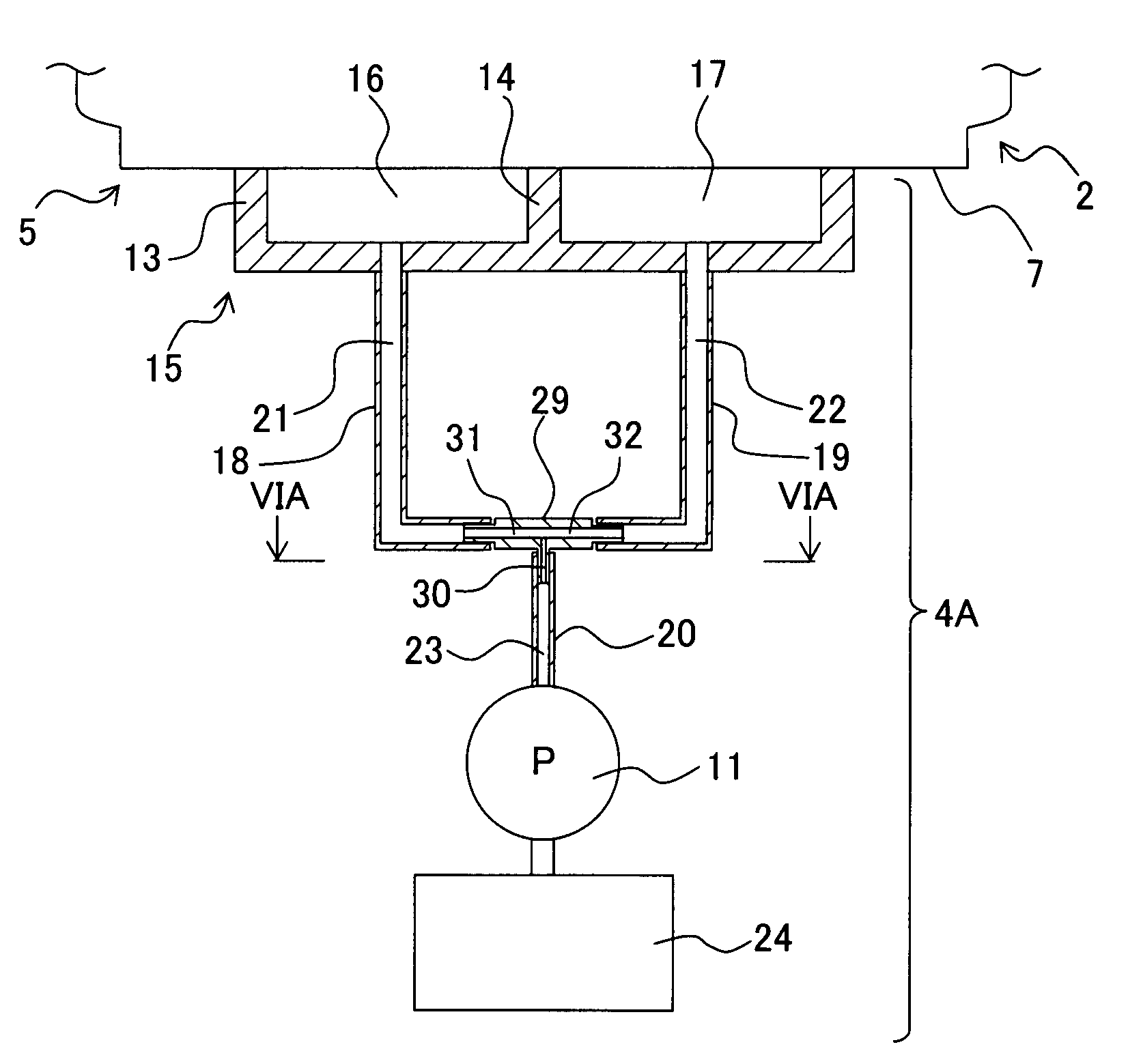
[0072]In a first modified embodiment shown in FIG. 5A, a waste-liquid discharging mechanism 4A includes a coupling 29 which connects the first tubes 18 and 19, and the second tube 20. The coupling 29 has a shape of an English alphabet T, and two first communicating portions 31 and 32 directed toward both sides are formed inside the coupling. Furthermore, a second communicating portion 30 which communicates with the first communicating portions 31 and 32 and which is directed downward is formed inside the coupling 29. By connecting the first tubes 18 and 19, the second tube 20, and the coupling 29, the first channels 21 and 22 of the first tubes 18 and 19 are connected to the first communicating portions 31 and 32 respectively, of the coupling 29, and the second channel 23 of the second tube 20 is connected to the second communicating portion 30 of the coupling 29. Accordingly, the first channels 21 and 22 communicate with the second channel 23 via the first communicating portions 31...
second modified embodiment
[0073]In a second modified embodiment shown in Fig. SB, since the communicating portion 30 which is long is formed in the coupling 29, the channel resistance of the second channel is higher than the channel resistance of the first channels 21 and 22.
third modified embodiment
[0074]FIG. 6A is a cross-sectional view taken along a line 6A-6A in FIG. 5A. A cross-sectional shape of the second communicating portion 30 shown in FIG. 6A is a ring shape. Whereas, in a third modified embodiment shown in FIG. 6B, a thick wall portion 300 is formed in a portion of a second communicating portion 30A, facing in a vertical direction in FIG. 6B. In other words, the thick wall portion 300 which decreases a gap of a surface facing an inner peripheral surface is formed in the second communicating portion 30A, and a cross-sectional area of the second communicating portion 30A is smaller than a cross-sectional area of the first channels 21 and 22. Since the thick wall portion 300 is formed in the second communicating portion 30A, the channel resistance of the second channel 23 is higher than the channel resistance of the first channels 21 and 22. A shape of such thick wall portion 300 is arbitrary, and the thick wall portion may be formed throughout a longitudinal direction...
PUM
 Abstract
Description
Claims
Application Information
 - Generate Ideas
- Intellectual Property
- Life Sciences
- Materials
- Tech Scout
- Unparalleled Data Quality
- Higher Quality Content
- 60% Fewer Hallucinations
Browse by: Latest US Patents, China's latest patents, Technical Efficacy Thesaurus, Application Domain, Technology Topic, Popular Technical Reports.
© 2025 PatSnap. All rights reserved.Legal|Privacy policy|Modern Slavery Act Transparency Statement|Sitemap|About US| Contact US: help@patsnap.com


