Temperature sensor capable of reducing test mode time

a temperature sensor and test mode technology, applied in the field of temperature sensors, can solve the problem of taking a lot of time to set up the reference level vest, and achieve the effect of reducing the test mode tim

Active Publication Date: 2011-12-20
SK HYNIX INC
View PDF8 Cites 4 Cited by
  • Summary
  • Abstract
  • Description
  • Claims
  • Application Information

AI Technical Summary

Benefits of technology

[0019]In an aspect of the present disclosure, a temperature sensor is provided that is capable of reducing a test mode time by internally producing a test pulse for a test mode.

Problems solved by technology

However, since the above-mentioned test mode continuously applies the test pulse Test_Pulse to the control signal generating unit until the reference level Vest corresponding to a predetermined internal temperature is set up, it takes a lot of time to set up the reference level Vest.

Method used


Image

  • Temperature sensor capable of reducing test mode time
  • Temperature sensor capable of reducing test mode time
  • Temperature sensor capable of reducing test mode time

Examples


Embodiment Construction

[0056]Hereinafter, embodiment of the present disclosure will be described with reference to accompanying drawings. However, the embodiment are for illustrative purposes only and are not intended to limit the scope of the invention.

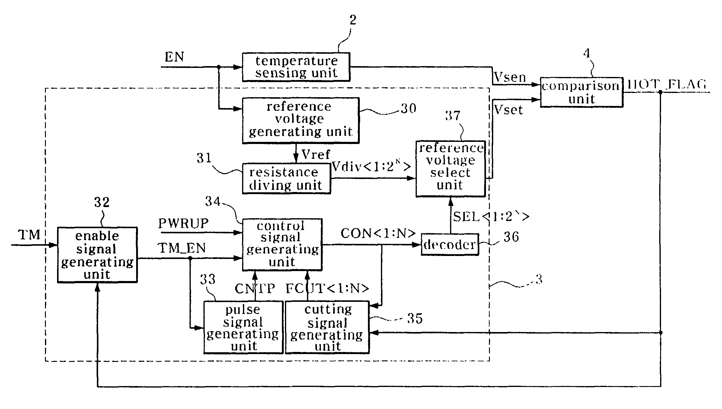
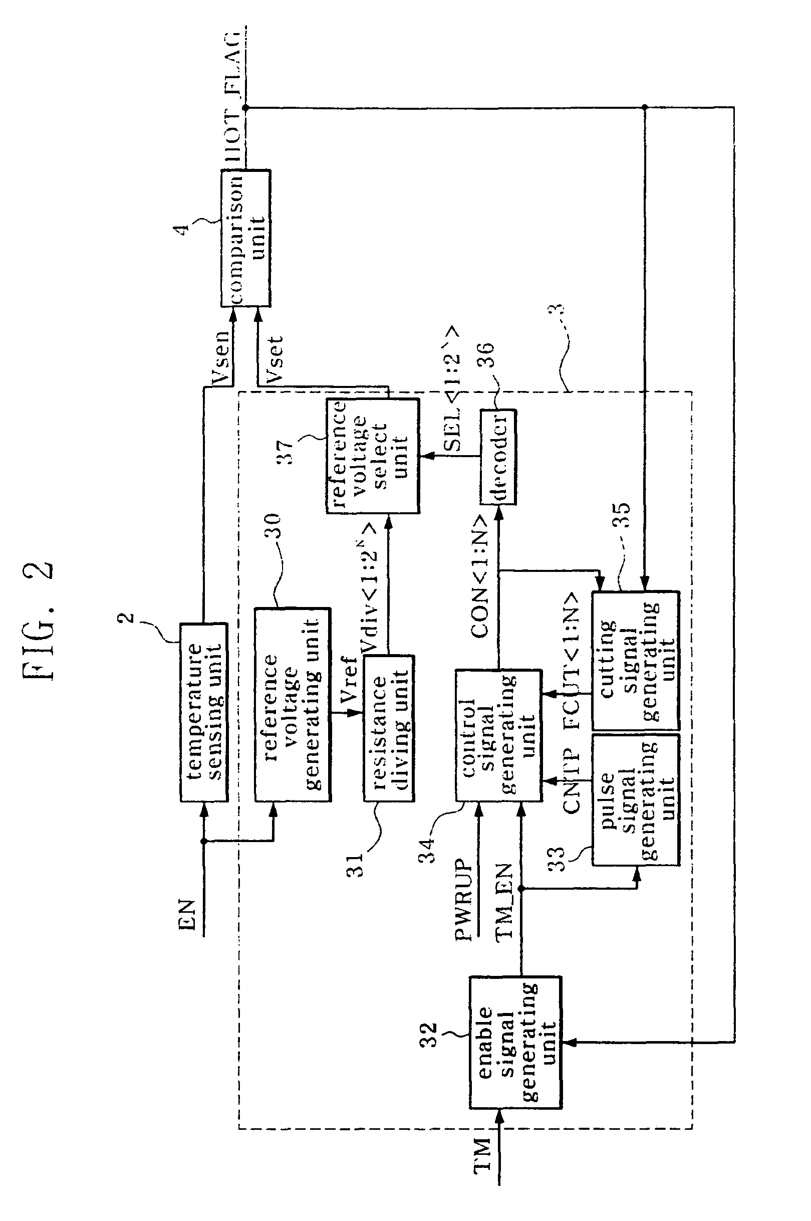
[0057]As shown in FIG. 2, a temperature sensor according an embodiment of the present disclosure includes a temperature sensing unit 2, a reference level generating unit 3, and a comparison unit 4.

[0058]The temperature sensing unit 2, which is driven by an enable signal EN, senses an internal temperature of a semiconductor memory device and produces a sensing level Vsen. The higher the internal temperature of the semiconductor memory device is, the less the voltage level of the sensing level Vsen is reduced.

[0059]The reference level generating unit 3 includes a reference voltage generating unit 30, a resistance dividing unit 31, an enable signal generating unit 32, a pulse signal generating unit 33, a control signal generating unit 34, a cutting signal gen...


PUM


Abstract

A temperature sensor includes a temperature sensing unit for producing a sensing level by sensing an internal temperature in a semiconductor memory device, a reference level generating unit for setting up a reference level by selecting one of a plurality of reference voltages, which are set up according to the internal temperature of the semiconductor memory device, in response to a test mode signal and a temperature detecting signal, wherein the reference level generating unit includes fuse, and a comparison unit for comparing the sensing level to the reference level and producing the temperature detecting signal.

Description

TECHNICAL FIELD[0001]The present disclosure relates to a temperature sensor and, more particularly, to a temperature sensor to provide a test mode which is capable of reducing a test mode time and setting up a reference level without an additional processing.BACKGROUND[0002]As known widely to those skilled in the art, a semiconductor memory device, such as a DRAM, has a temperature sensor for controlling an operation of internal circuits based on an internal temperature. The temperature information produced by the temperature sensor is used to control the self-refresh period through a detection of the surrounding temperature in order that current consumption is reduced in a self-refresh operation or is used for deciding whether a detected temperature is higher than a predetermined temperature.[0003]FIG. 1 is a block diagram illustrating a conventional temperature sensor.[0004]Referring to FIG. 1, the conventional temperature sensor includes a temperature sensing unit 10 to produce a...

Claims


Application Information

Patent Timeline
IPC IPC(8): G11C7/04
CPCG01K15/00G11C5/143G11C29/02G11C29/028G11C2029/5002G01K15/007
Inventor LEE, SEONG SEOP
Owner SK HYNIX INC
Why Eureka
Try Eureka