Controller gain scheduling for mass flow controllers

a controller and mass flow technology, applied in adaptive control, process and machine control, instruments, etc., can solve the problems of unnecessarily complicated approach, high control problem, and two common control performance problems

Active Publication Date: 2011-12-20
MKS INSTR INC
View PDF13 Cites 10 Cited by
  • Summary
  • Abstract
  • Description
  • Claims
  • Application Information

AI Technical Summary

Benefits of technology

[0015]A mass flow controller having a feedback controller gain, comprises: a sensor configured so as to sense the flow of fluid through controller; a valve arranged so as to adjust the flow of fluid through the controller; and a processor configured so as to control the valve as a function of the flow of fluid sensed by the sensor. The sensor and valve are arranged within a feedback system, and the processor updates the feedback controller gain in real time based on the ratio of at least one calibration gas parameter to at least one operating gas parameter, such that the closed loop transfer function of the feedback system remains substantially constant regardless of operating conditions so as to have a consistent control performance at different operation conditions from the calibration condition.

Problems solved by technology

Two common control performance issues often occur for a MFC operating in a condition different from the calibration condition such as different gas type, different inlet gas pressure, or different inlet gas temperature.
This issue is related to a low controller gain setting when the inlet gas is switched from Nitrogen to a light weight gas such as Helium or the inlet gas pressure changes from high pressure to low pressure.
This issue is related to a high controller gain setting when the inlet gas is switched from Nitrogen to a heavy weight gas such as SF6 or the inlet gas pressure changes from low pressure to high pressure.
These control issues are highly problematic in semiconductor manufacturing processes that require careful, high precision, time control of fluid flow rates
However, this approach is unnecessarily complicated.

Method used


Image

  • Controller gain scheduling for mass flow controllers
  • Controller gain scheduling for mass flow controllers
  • Controller gain scheduling for mass flow controllers

Examples


Embodiment Construction

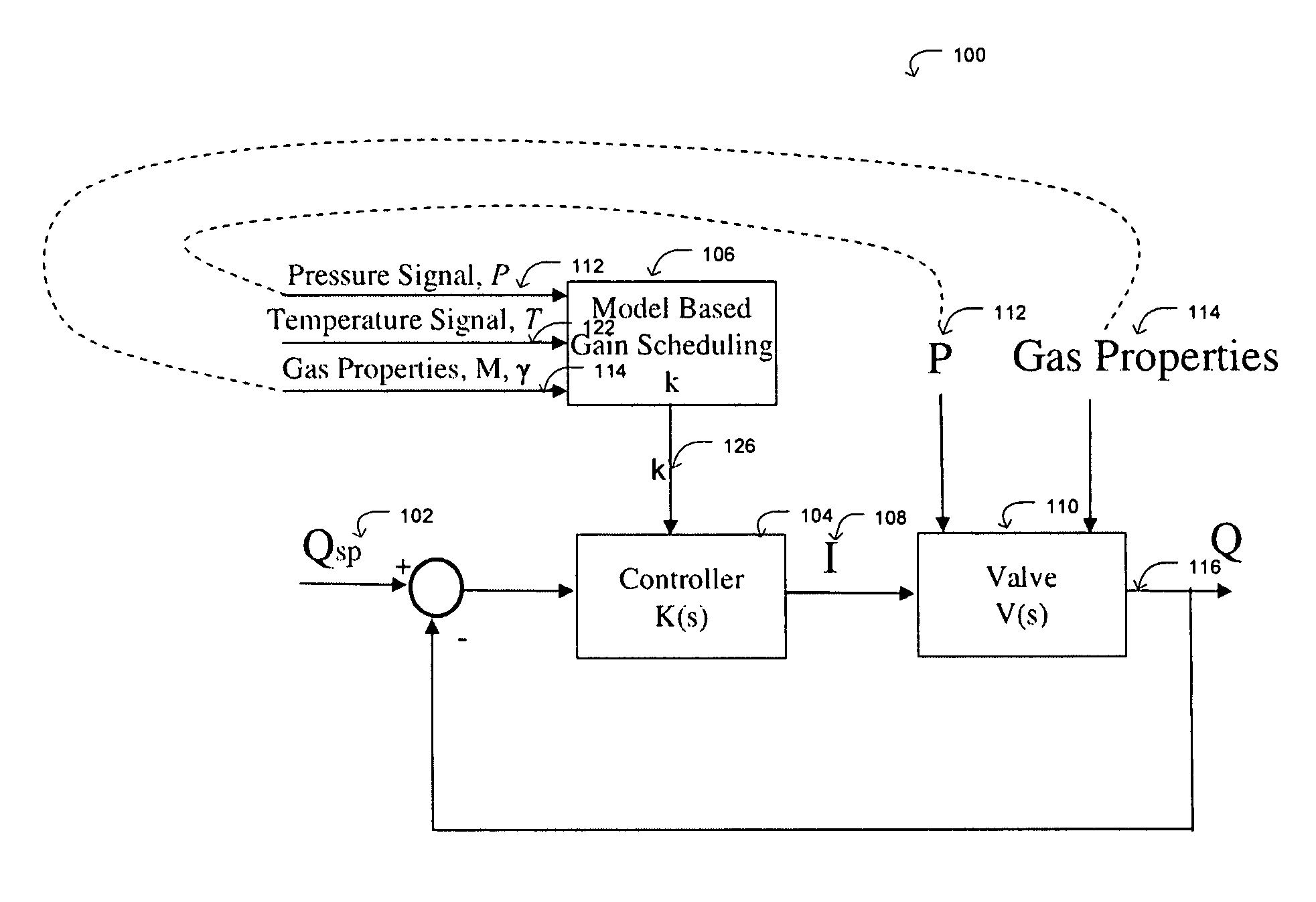
[0020]Referring to an embodiment shown in FIG. 3, the block diagram of a MFC control system 100 includes a negative feedback control loop. Feedback control systems generally include an input and an output, and a relationship that couples the output with the input. In this feedback control loop, Qsp 102 (the desired set point flow rate) is the input. A resulting actual rate of flow Q, indicated at 116 is the output. In the following description, all time domain variables such as Q(t) and Qsp(t) are transformed to LaPlace domain as Q(s) and Qsp(s) which is a common practice used in control area.

[0021]The physical model of the control system 100 includes a controller K(s), indicated at 104, and a valve V(s), indicated at 110. The feedback controller K(s) generates a control command current I(s), indicated at 108 so as to adjust the openness of the valve such that the output of the valve, the actual flow rate Q(s), tracks the desired set point flow rate Qsp(s) 102. Here, we assume that ...


PUM


Abstract

A mass flow controller having a feedback controller gain, comprises: a sensor configured so as to sense the flow of fluid through controller; a valve arranged so as to adjust the flow of fluid through the controller; and a processor configured so as to control the valve as a function of the flow of fluid sensed by the sensor. The sensor and valve are arranged within a feedback system, and the processor updates the feedback controller gain in real time based on the ratio of at least one calibration gas parameter to at least one operating gas parameter, such that the closed loop transfer function of the feedback system remains substantially constant regardless of operating conditions so as to have a consistent control performance at different operation conditions from the calibration condition.

Description

BACKGROUND[0001]1. Field[0002]The present disclosed embodiments relate generally to measurement and control of fluid flow, and more specifically to model-based controller gain scheduling for mass flow controllers.[0003]2. Background[0004]A mass flow controller (MFC) is a device that sets, measures, and controls the rate and amount of fluid, such as a gas or vapor, passing through the device. These devices are designed and calibrated to control with high precision the flow of gas within a predefined range of flow rates.[0005]Some manufacturing processes, such as semiconductor manufacturing, require precise control of the rate of flow and the amount (mass) of gases and vapors delivered to a process chamber or tool. Often, precise fluid flow rates and amounts (the total mass of fluid) are critical to ensure optimal results. Applications include metering of precise amounts of gases and vapors flowing into a process chamber for subsequent deposition on work pieces, dry etching to remove ...

Claims


Application Information

Patent Timeline
Patent Type & Authority Patents(United States)
IPC IPC(8): G05D7/06
CPCG01F1/68G01F15/005G01F25/0007G05B13/042G05D7/0635Y10T137/7759Y10T137/7761G01F25/10G01F15/00G01F25/00G05B13/04
Inventor DING, JUNHUA
Owner MKS INSTR INC
Why Eureka
Try Eureka