Method and system for producing a hydrogen enriched fuel using microwave assisted methane decomposition on catalyst

a technology of methane decomposition and catalyst, which is applied in the direction of hydrocarbon preparation, inorganic chemistry, component separation, etc., can solve the problems of methane gas not being able to react, and achieve the effect of minimizing costs

Active Publication Date: 2011-12-13
EDEN ENERGY
View PDF79 Cites 16 Cited by
  • Summary
  • Abstract
  • Description
  • Claims
  • Application Information

AI Technical Summary

Benefits of technology

[0014]The method can be performed in a reactor having a reaction chamber with microwave transparent walls. In addition, the catalyst can comprise a metal, such as a Ni-based compound prepared by coprecipitation. On the surface of the catalyst reactions occur in which methane (CH4) dissociates into hydrogen (H2) and solid carbon (C) in the form of fibrous carbon. In addition, some of the methane gas fails to react (methane slip) such that the product gas comprises methane and hydrogen. The catalyst is selected and formulated to remain stable under operating conditions (e.g., gas flow rate, microwave power, catalyst amount), such that costs are minimized. In addition, the catalyst maintains active characteristics through many hours of reactions.

Problems solved by technology

In addition, some of the methane gas fails to react (methane slip) such that the product gas comprises methane and hydrogen.

Method used


Image

  • Method and system for producing a hydrogen enriched fuel using microwave assisted methane decomposition on catalyst
  • Method and system for producing a hydrogen enriched fuel using microwave assisted methane decomposition on catalyst
  • Method and system for producing a hydrogen enriched fuel using microwave assisted methane decomposition on catalyst

Examples


example 1

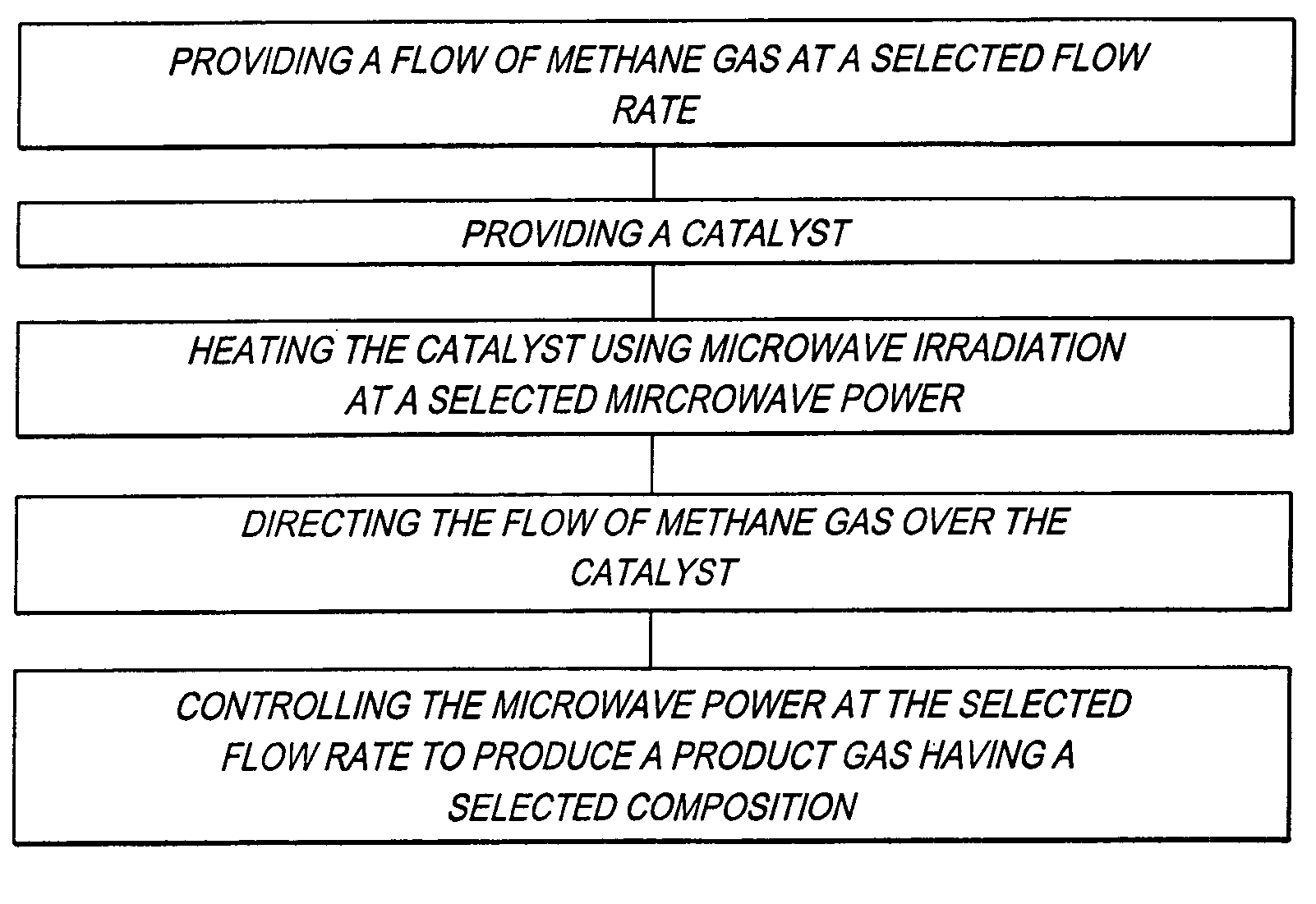
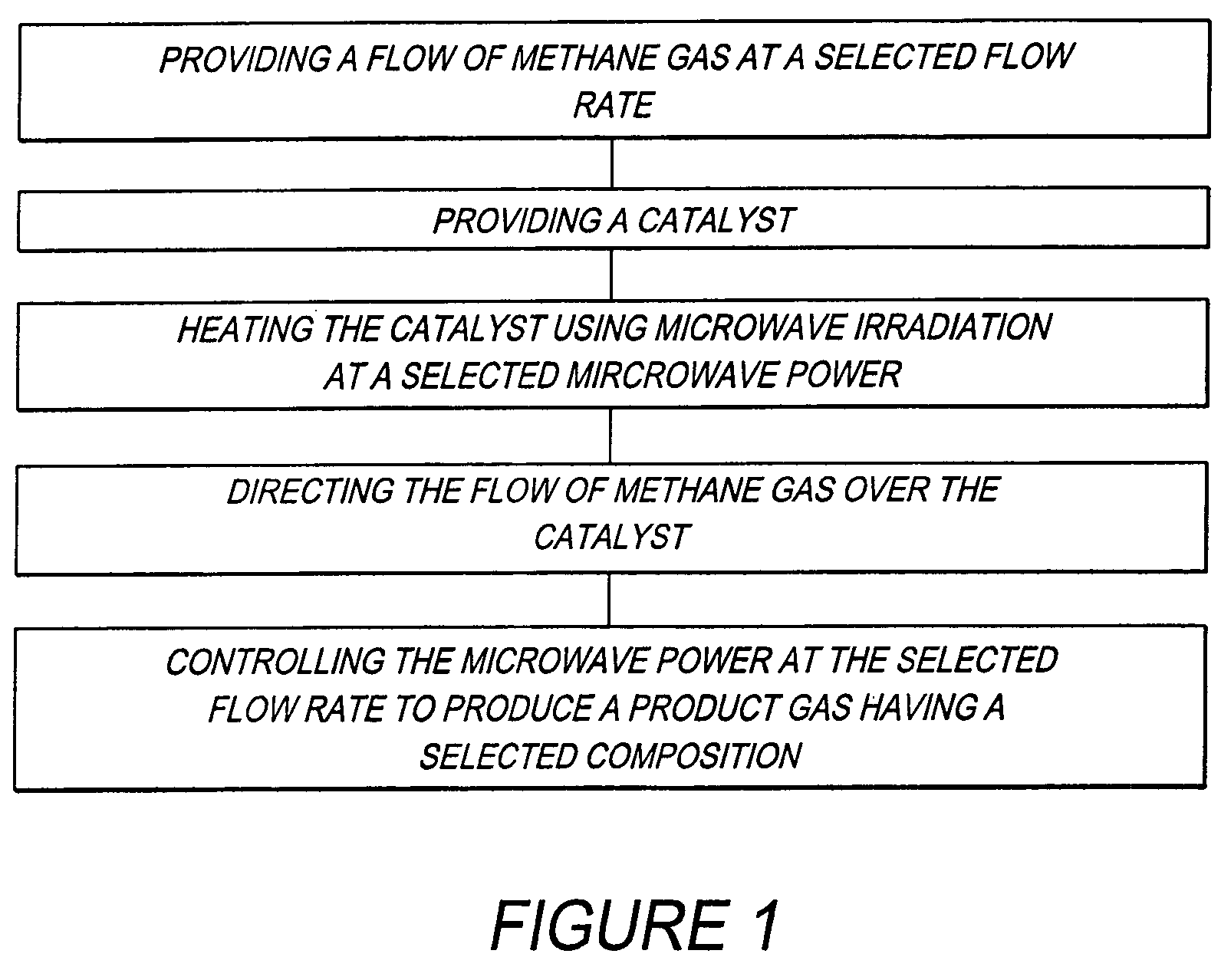
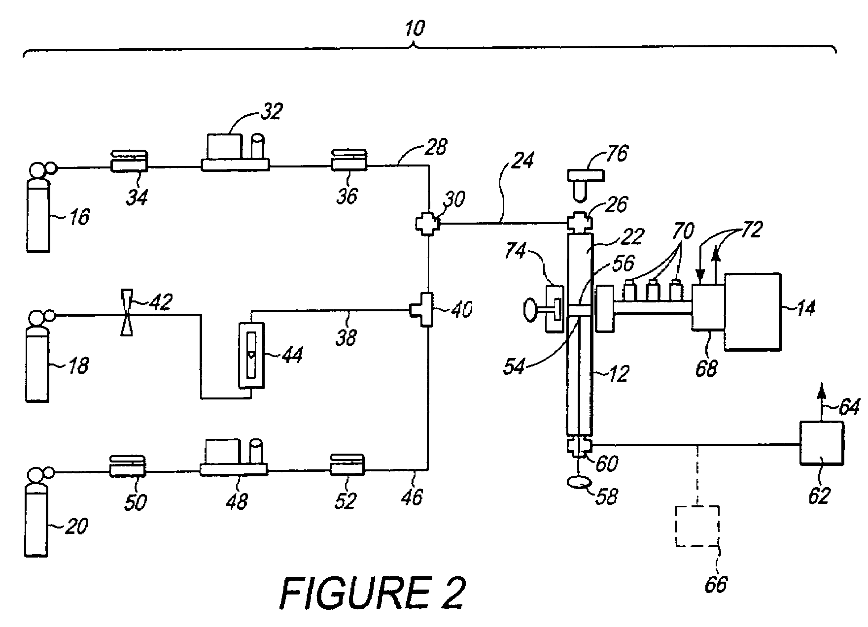
[0051]Using the previously described method (FIG. 1), and the previously described system 10 (FIG. 2), a hydrogen enriched fuel comprising CH4 and H2 was produced under the following conditions.[0052]A. Pure methane gas (99.7% purity) was supplied through the methane supply conduit 28 to the reactor 12 (FIG. 12).[0053]B. Methane flow rate (i.e., selected flow rate in FIG. 1): 120 ml / minute.[0054]C. Catalyst 56 (FIG. 2): Ni54Cu27Al.[0055]D. The catalyst 56 (FIG. 2) was initially reduced for a period of several minutes in H2 plasma at a microwave power of 160 W. For reducing the catalyst 56 (FIG. 2), a flow of H2 gas was supplied through the hydrogen supply conduit 38 (FIG. 2) to the reaction chamber 22 (FIG. 2), and irradiated with microwave energy from the microwave generator 14 (FIG. 2) to form a plasma.[0056]E. Reaction pressure: atmospheric pressure (1 atm).[0057]F. Products (hydrogen enriched fuel): H2, solid carbon C and unreacted CH4, by the reaction CH4=C+2H2. SEM (scanning e...

example 2

[0065]Example 2 was performed using the same conditions as outlined above for Example 1 but with the catalyst comprising Ni81Al rather than Ni54Cu27Al.

[0066]FIG. 4 illustrates the results of CH4 conversion assisted by microwave heating using Ni81Al as the catalyst 56 (FIG. 2). Example 2 was a continuous process. In FIG. 4, the reaction time in hours (h) denotes the length of time that the process was performed.

[0067]In FIG. 4 there are three separate graphs. The lower graph plots the conversion rate “X %” of the CH4 on the y-axis (expressed as a volume percentage) versus the reaction time in hours on the x-axis. The middle graph plots the content “C %” of H2 on the y-axis (expressed as a volume percentage) versus the reaction time in hours on the x-axis. The upper graph plots the amount of solid carbon (Solid C (g)) on the y-axis (expressed in grams) versus the reaction time in hours on the x-axis.

[0068]From these two examples it was determined that a product gas containing 30% by v...


PUM

PropertyMeasurementUnit
diameteraaaaaaaaaa
microwave poweraaaaaaaaaa
temperatureaaaaaaaaaa

Abstract

A method for producing a hydrogen enriched fuel includes the steps of providing a flow of methane gas, and providing a catalyst. The method also includes the steps of heating the catalyst instead of the reactor walls and the methane gas using microwave irradiation at a selected microwave power, directing the flow of methane gas over the catalyst, and controlling the microwave power to produce a product gas having a selected composition. A system for producing a hydrogen enriched fuel includes a methane gas source, a reactor containing a catalyst, and a microwave power source configured to heat the catalyst.

Description

CROSS REFERENCE TO RELATED APPLICATIONS[0001]This application is related to Ser. No. 11 / 657,299, filed Jan. 25, 2007, Publication No. US-2008-0181845-A1; to Ser. No. 12 / 030,970, filed Feb. 14, 2008, Publication No. US-2009-0205254-A1; and to Ser. no. 12 / 040,883, filed Mar. 01, 2008, Publication No. US-2008-0210908-A1.FIELD OF THE INVENTION[0002]This invention relates generally to the production of hydrogen fuels, and particularly to a method and a system for producing a hydrogen enriched fuel suitable for use as an alternative fuel.BACKGROUND OF THE INVENTION[0003]Gaseous alternative fuels, such as hydrogen and natural gas, are valued for their clean burning characteristics in motor vehicle engines. Various processes have been developed for producing hydrogen. These processes include electrolysis, exotic water splitting, and separation from industrial waste streams.[0004]Hydrogen can also be produced by reforming natural gas. Typically, a multi-step process is used to convert a hydr...

Claims


Application Information

Patent Timeline
Patent Type & Authority Patents(United States)
IPC IPC(8): C01B3/26
CPCC01B3/26C01B3/505C01B2203/0277C01B2203/0405C01B2203/041C01B2203/048C01B2203/0855C01B2203/1058C01B2203/1076C01B2203/1241C01B2203/16C01B2203/1619C01B2203/1671C01B2203/168C01B2203/169B01J19/08C01B3/46
Inventor ZHU, ZHONGHUA JOHNCHEN, JIULINGLU, GAOQING MAXSOLOMON, GREGORY
Owner EDEN ENERGY
Why Eureka
Try Eureka