
Hybrid drive train of a motor vehicle

a hybrid drive and motor vehicle technology, applied in hybrid vehicles, gearing, vehicle sub-unit features, etc., can solve the problems of poor driving performance, less comfort, unfavorable low overall gear ratio of electric motor compared to output shaft, etc., to achieve simple and space-saving construction, improve controllability, and high overall gear ratio of electric motor

Inactive Publication Date: 2011-12-13
ZF FRIEDRICHSHAFEN AG
View PDF10 Cites 65 Cited by
  • Summary
  • Abstract
  • Description
  • Claims
  • Application Information

AI Technical Summary

Benefits of technology

The invention proposes a hybrid drive train for a motor vehicle that allows for a high overall gear ratio and improved control of the electric motor. The drive train includes a decoupler, two input shafts, and a differential transmission. The gearwheel sets and clutches can be assigned to the two input shafts in a variety of ways to achieve the desired gear ratios. The hybrid drive train is simple and space-saving, and it provides high efficiency and improved control of the electric motor.

Problems solved by technology

However, one disadvantage of this kind of hybrid drive train is that the engine-speed level of the electric motor is identical to that of the internal combustion engine, and the electric motor must therefore be constructed as relatively large and heavy in order to achieve adequate output in the electrically powered mode.
However, a significant disadvantage of this hybrid drive train is the interruption in the flow of force during shifting operations, which results in poor driving performance and less comfort.
Purely electric drive operation, with the electric motor as the only drive engine, is possible with a disengaged decoupler and with an engaged gear in the gearshift, but even with an engaged first gear, particularly in order to start the vehicle, this would produce an unfavorably low overall gear ratio of the electric motor compared to the output shaft.
In this way, the shifting operations take place without interruption of traction, but are relatively elaborate and time-consuming.
However, because of the two decouplers, the input constants, the axially parallel arrangement of the electric motor and the axially adjacent arrangement of the gearwheel sets, the constructional complexity and construction space requirements of this known hybrid drive train are unfavorable.

Method used


Image

  • Hybrid drive train of a motor vehicle
  • Hybrid drive train of a motor vehicle
  • Hybrid drive train of a motor vehicle

Examples


Embodiment Construction

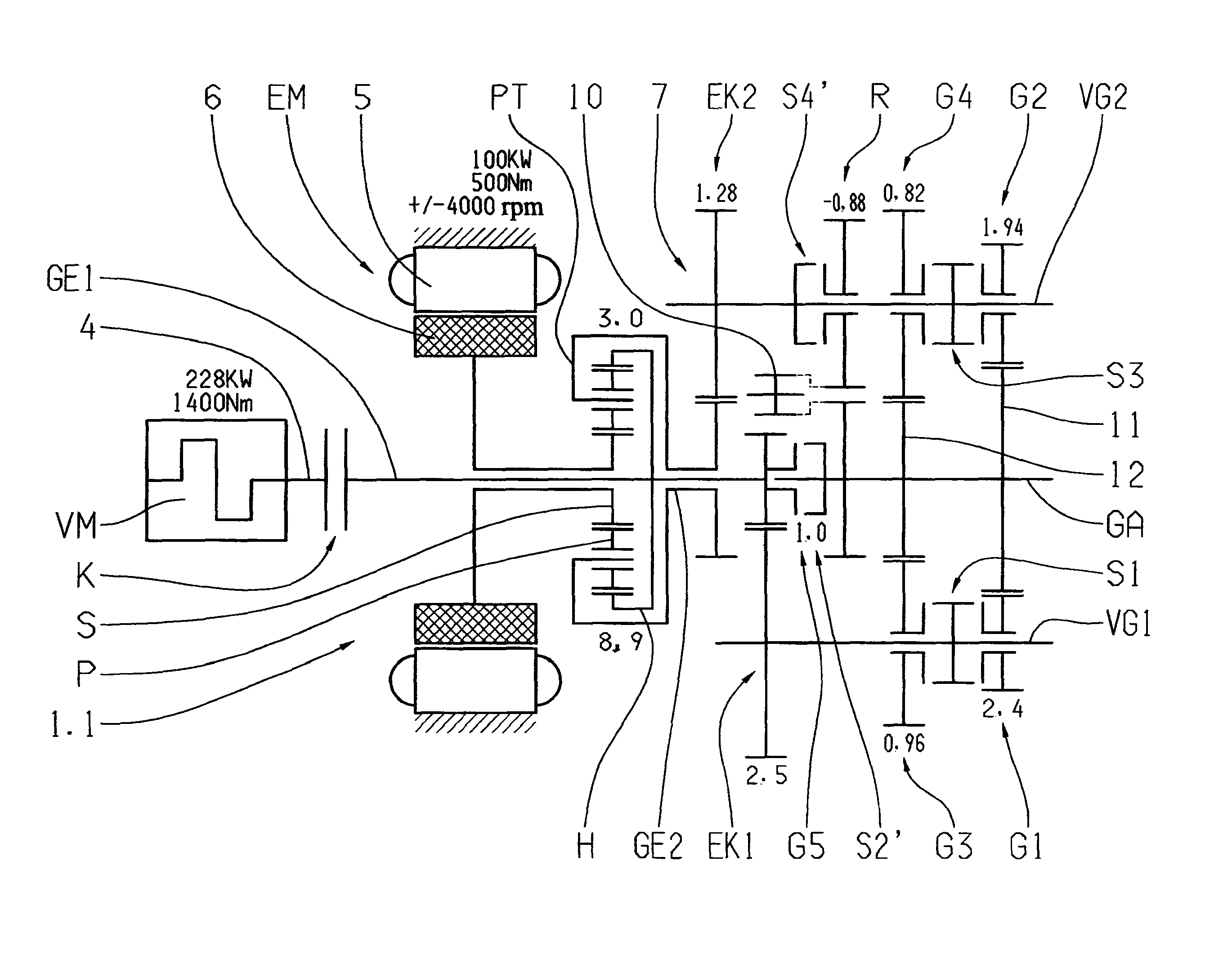
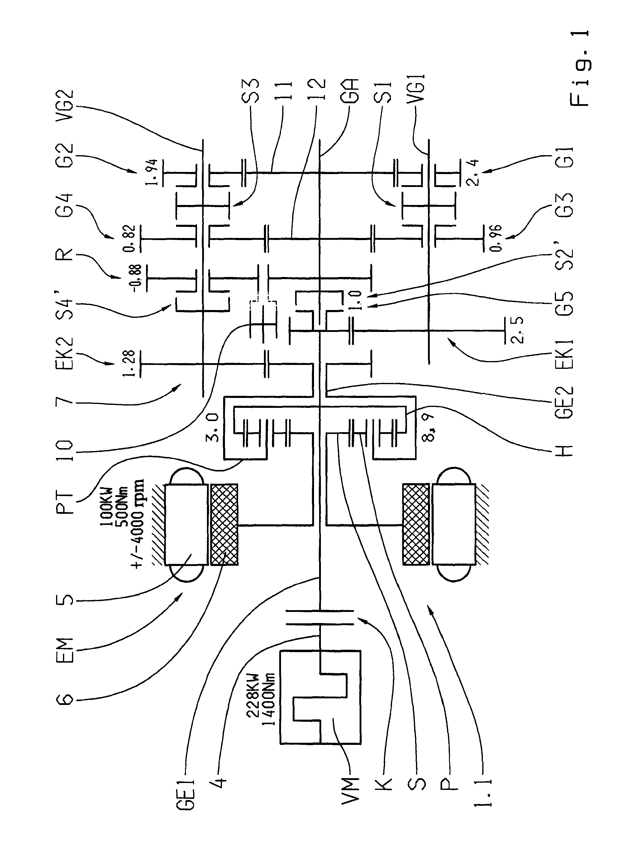
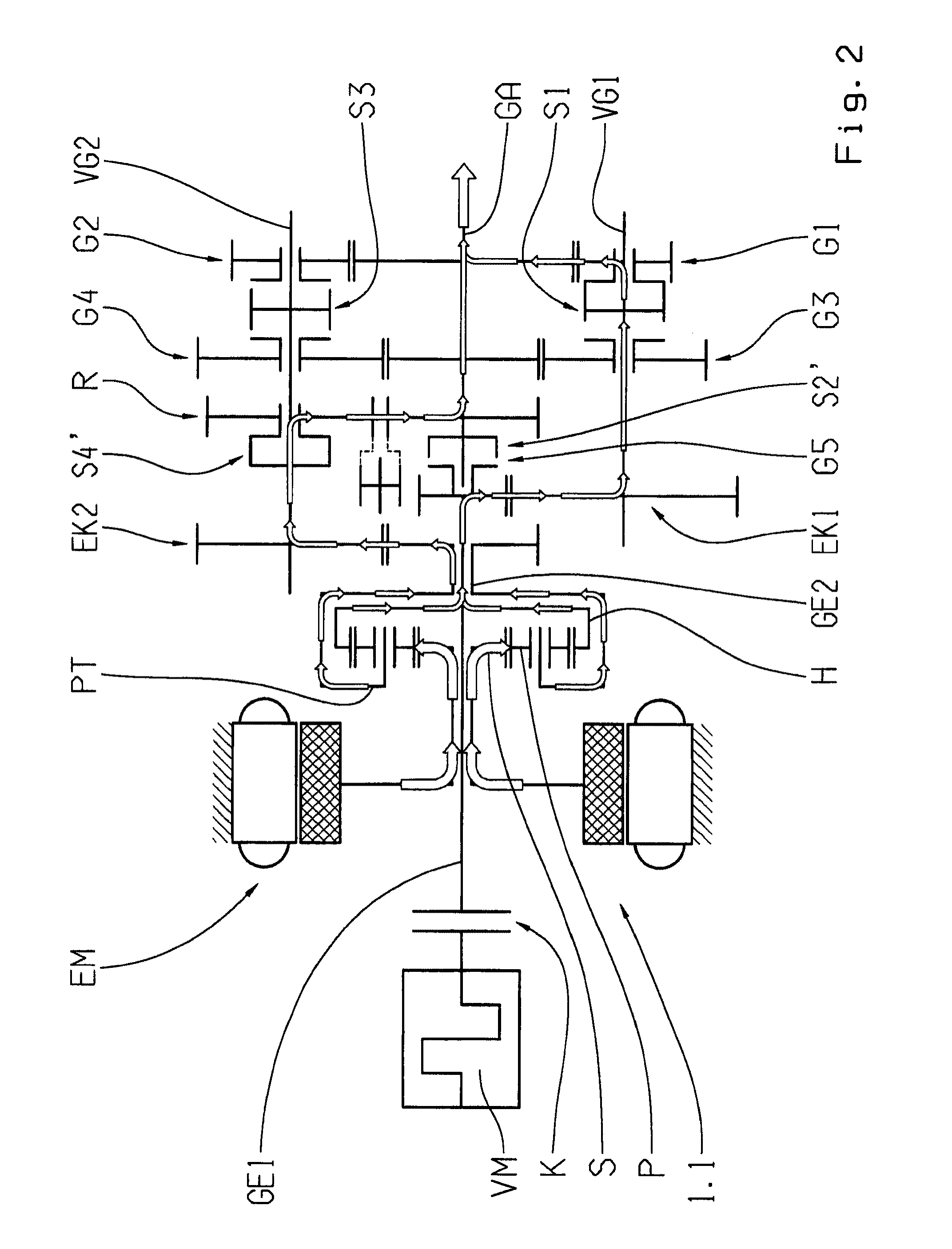
[0062]In FIG. 1, a first embodiment of the hybrid train of the invention 1.1 is shown in schematic form. This hybrid drive train 1.1 comprises an internal combustion engine VM with a driveshaft 4, an electric motor EM that can be operated as a motor and a generator, with a stator 5 and a rotor 6, a multi-step transmission 7 with two input shafts GE1, GE2, and an output shaft GA, and a differential transmission with three drive elements.

[0063]The first input shaft GE1 of the transmission 7 can be connected to the driveshaft 4 of the internal combustion engine VM by means of an assigned decoupler K. The differential transmission 8 is designed as a simple planetary gearset 9 with a sun gear S, a planet carrier PT, and a ring gear H, whereby the planet carrier PT carries a plurality of rotateable planetary gears P, each of which is in interlocking engagement with the sun gear S and the ring gear H. The planetary gearset 9 is arranged coaxially about the first input shaft GE1. The ring g...


PUM


Abstract

A hybrid gear train of a motor vehicle that has an internal combustion engine with a drive shaft, an electric motor with a rotor that operate as a motor and a generator, a transmission with two input shafts and an output shaft, as well as a differential transmission. At least one of the input shafts can be connected, via an assigned de-coupler, to the drive shaft, both of the input shafts can be connected by alternately assigned gearwheel sets of different ratios and in each case one assigned gear clutch to the output shaft. The differential transmission is designed as a simple planetary gearset that is coaxial with the first input shaft. The ring gear of this transmission is rotationally fixed to the one input shaft. The planet carrier is rotationally fixed to the second input shaft, and the sun gear is connected to and drives the rotor.

Description

[0001]This application is a National Stage completion of PCT / EP2007 / 063118 filed Dec. 3, 2007, which claims priority from German patent application serial no. 10 2006 059 591.2 filed Dec. 16, 2006.FIELD OF THE INVENTION[0002]The invention relates to a hybrid drive train of a motor vehicle that comprises an internal combustion engine with a driveshaft, an electric motor that can be operated as an engine and a generator and has a rotor, a multi-stage manual transmission with two input shafts and one output shaft, as well as a differential transmission, whereby at least one of the input shafts can be can be connected to the driveshaft by means of an assigned decoupler. Both input shafts can be selectively connected to the output shaft by means of alternately assigned gearwheel sets of different ratios and respectively one assigned gear clutch. The differential transmission is designed as a simple planetary gearset that is arranged coaxially with the first input shaft. The ring gear the...

Claims


Application Information

Patent Timeline
Patent Type & Authority Patents(United States)
IPC IPC(8): F16H3/72B60L50/16B60W10/10B60W30/18
CPCB60K6/365B60K6/547B60W10/02B60W10/06B60W10/08B60W10/11B60W30/18027F16H3/725B60K6/48Y10T477/26B60L2240/421B60W20/00B60W2710/081B60Y2400/428F16H3/006F16H2200/0052F16H2200/2005Y02T10/6221Y02T10/6286Y02T10/642Y10T477/23Y02T10/62Y02T10/64B60K2006/268B60K6/00B60W2050/0001
Inventor BACHMANN, MAX
Owner ZF FRIEDRICHSHAFEN AG
Learn More