
Fiber air turn for low attenuation fiber

a low attenuation, fiber air technology, applied in the direction of manufacturing tools, lighting and heating equipment, furniture, etc., can solve the problems of adding height to an existing system, and reducing the efficiency of cooling fibers

Active Publication Date: 2011-12-13
CORNING INC
View PDF60 Cites 29 Cited by
  • Summary
  • Abstract
  • Description
  • Claims
  • Application Information

AI Technical Summary

Benefits of technology

This approach reduces the sensitivity of optical fibers to heat aging and Rayleigh scattering, minimizing attenuation over time and enabling high-speed, high-tension fiber production with reduced defects.

Problems solved by technology

Furthermore, attenuation may be the result of Rayleigh scattering loss.
However, cooling fiber at a controlled rate can be difficult to achieve in conventional processes for manufacturing optical fibers.
Because adding height to an existing system can add significant cost to the system, processing systems in which space is available for controlled cooling without necessitating an increase in overall system height are desired.

Method used


Image

  • Fiber air turn for low attenuation fiber
  • Fiber air turn for low attenuation fiber
  • Fiber air turn for low attenuation fiber

Examples


examples

The invention will be further clarified by the following examples.

examples 1-12

Examples 1-12, representing various embodiments of the present invention, are set forth in Table 1. These examples show the treatment of optical fiber through a treatment zone having the indicated length L in meters, the indicated draw speed of the optical fiber through the treatment zone in meters per second, the indicated fiber surface temperature upon entry of the fiber into the treatment zone in ° C., the indicated fiber surface temperature upon exit of the fiber from the treatment zone in ° C., and the calculated average cooling rate of the fiber while in the treatment zone in ° C. per second.

TABLE 1Treat-AveragementFiber EntryFiber ExitCoolingEx-ZoneSurfaceSurfaceRate inam-LengthFiber DrawTemperatureTemperatureTreatmentple(meters)Speed (m / s)(° C.)(° C.)Zone (° C. / s)1510175012501000251016501350600352017501250200045201650135012005530175012503000653016501350180077.51517501250100087.5151650135060097.525175012501667107.525165013501000117.535175012502333127.535165013501400


PUM

PropertyMeasurementUnit
surface temperatureaaaaaaaaaa
lengthaaaaaaaaaa
total residence timeaaaaaaaaaa

Abstract

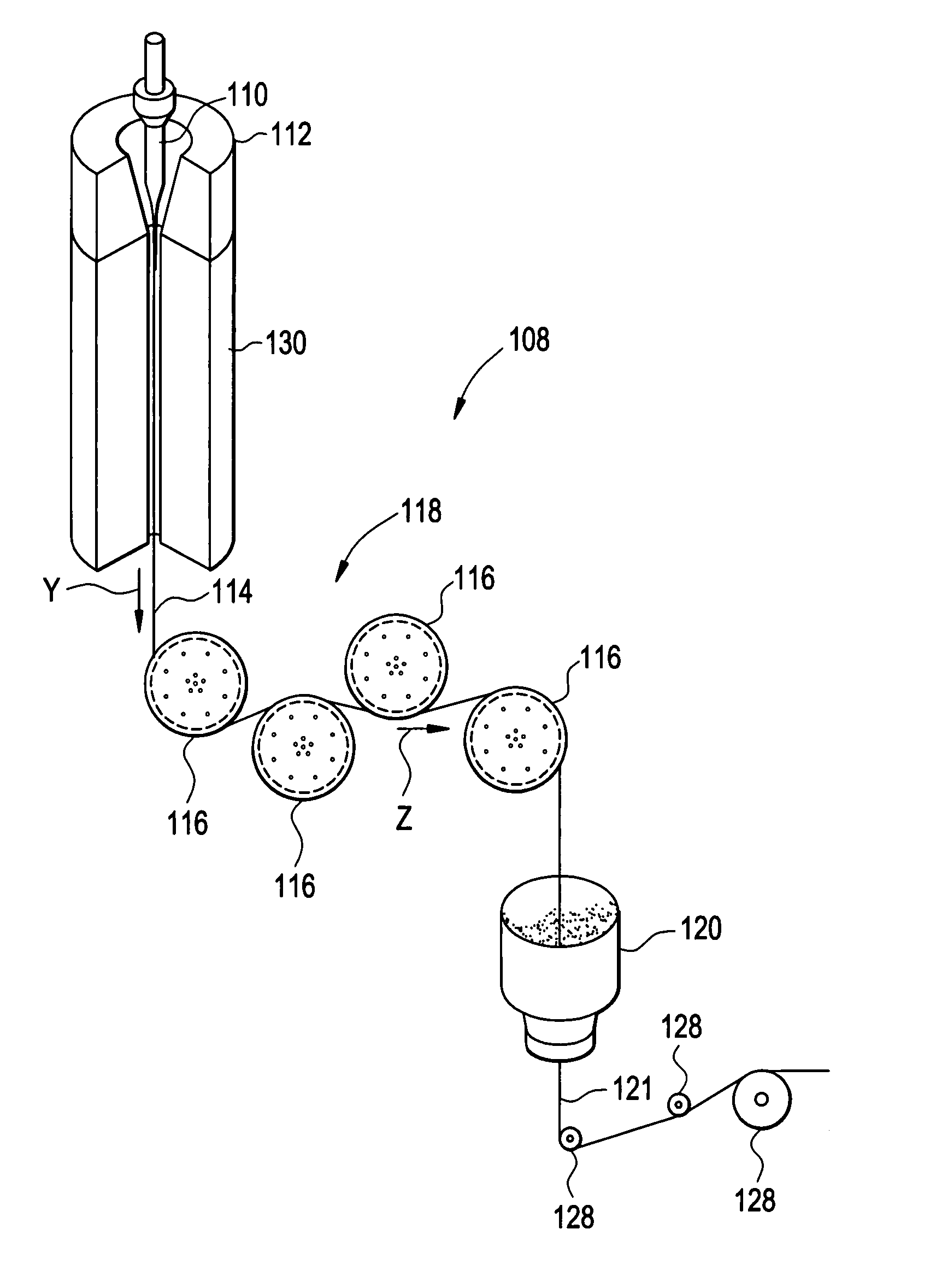
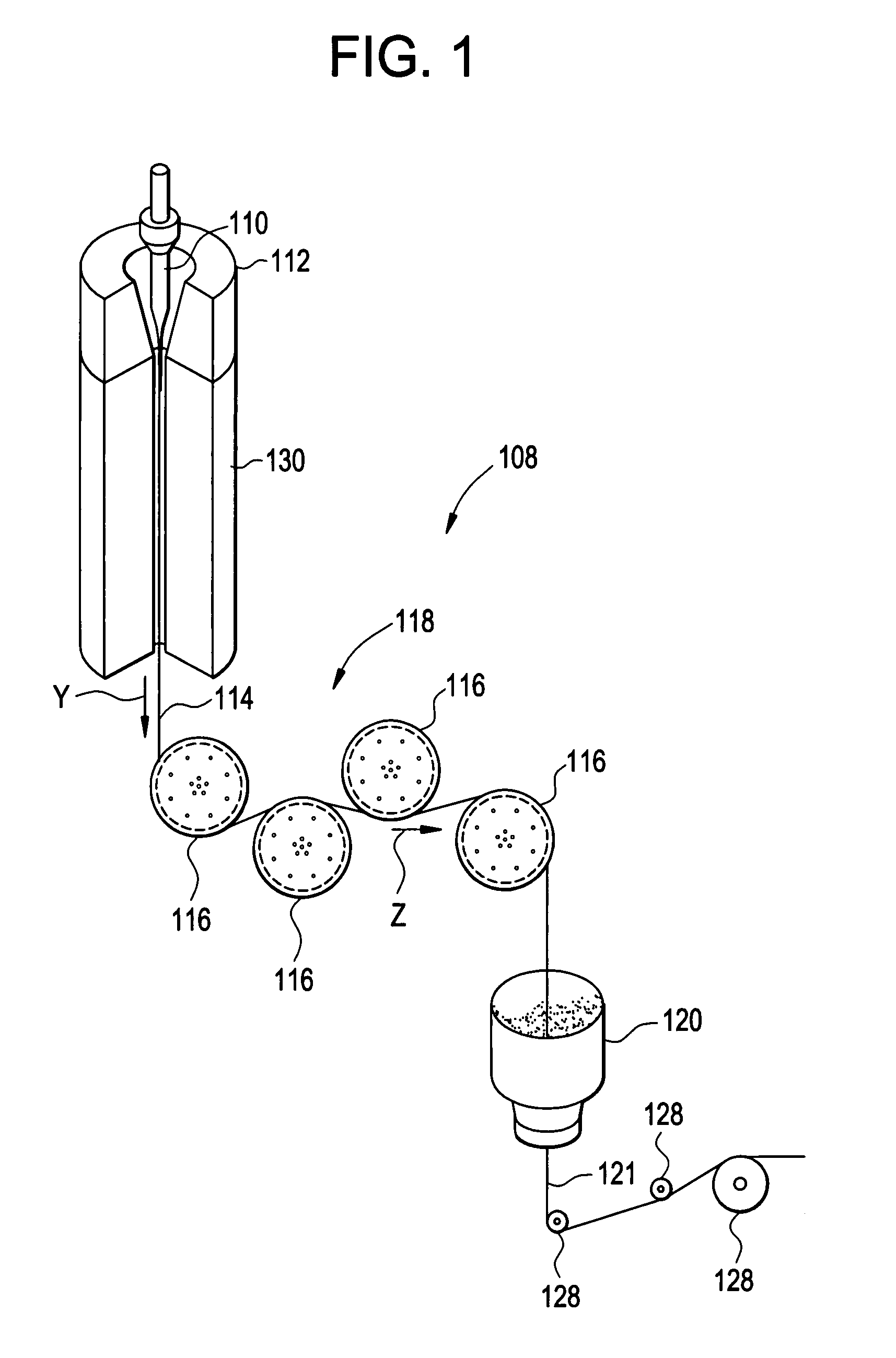
A method for forming an optical fiber includes drawing the optical fiber from a glass supply and treating the fiber by maintaining the optical fiber in a treatment zone wherein the fiber is cooled at a specified cooling rate. The optical fiber treatment reduces the tendency of the optical fiber to increase in attenuation due to Rayleigh scattering, and / or over time following formation of the optical fiber due to heat aging. Methods for producing optical fibers along nonlinear paths incorporating fluid bearings are also provided thereby allowing for increased vertical space for the fiber treatment zone.

Description

BACKGROUND OF THE INVENTION1. Field of the InventionThe present invention relates to methods and apparatus for forming optical fiber and more particularly, to methods and apparatus for forming optical fiber having improved characteristics.2. Technical BackgroundAttenuation and sensitivity to heat (or thermal) aging may be critical attributes of optical fibers, particularly for high data rate optical fibers. In making optical fibers, it may be necessary or desirable to minimize attenuation loss in the intended window of operation for the fiber. Attenuation in an optical fiber can increase after fabrication of the fiber because of a phenomenon called “heat aging.” Heat aging is the tendency of some optical fibers to increase in attenuation over time following formation of the fibers due to temperature fluctuations in the fiber's environment. Typically, the attenuation change from heat aging may be apparent at approximately 1200 nanometers (nm) with increasing effect up to about 1700 n...

Claims


Application Information

Patent Timeline
Patent Type & Authority Patents(United States)
IPC IPC(8): C03B37/02
CPCC03B37/02718C03B37/032C03B2205/42Y02P40/57
Inventor FILIPPOV, ANDREY VMATTHEWS, III, HAZEL BREDING, BRUCE WARRENSHEPARD, BRADLEY KTUCKER, DAVID ANDREW
Owner CORNING INC
Learn More