
Polarizing beam splitter, projection optical system, projection display

a technology of optical system and projection display, applied in the field of optical prisms, can solve the problems of deteriorating the resolution of projected image, etc., and achieve the effects of suppressing astigmatism, improving the focusing performance of projection optical device or projection display, and suppressing astigmatism

Inactive Publication Date: 2011-11-29
SONY CORP
View PDF17 Cites 10 Cited by
  • Summary
  • Abstract
  • Description
  • Claims
  • Application Information

AI Technical Summary

Benefits of technology

The patent text describes a problem with astigmatism in a polarizing beam splitter used in projection optical devices. Astigmatism occurs when there is a difference in refractive index between the prisms and the flat layers in the splitter, causing the image to be distorted. The text proposes a solution using a polarizing beam splitter with parallel flat layers to reduce astigmatism. The technical effect of this solution is to improve the resolution of the projected image and to simplify the structure of the projection optical device.

Problems solved by technology

However, the configuration using the known DBEF-D film for the polarization separating element or the configuration using the wire-grid polarization separating element has a problem with astigmatism.
When the astigmatism occurs, an in-focus position in a direction is different from an in-focus position in a direction perpendicular to the direction, thereby greatly deteriorating the resolution.
In this case, since the wire-grid polarization separating element is not rotationally symmetric about the optical axis of the projection lens, the astigmatism is caused, thereby deteriorating the resolution of the projected image.
In this case, however, the degree of flatness of the glass substrate is reduced to cause a distortion of the wire-grid polarization separating element, thereby deteriorating the resolution of the projected image.
In this case, however, the number of unnecessary components increases to complicate the structure of the projection optical system.
Since the back-focus of the projection lens need be enhanced, the size and the cost increase.
Accordingly, the method is not desirable.

Method used


Image

  • Polarizing beam splitter, projection optical system, projection display
  • Polarizing beam splitter, projection optical system, projection display
  • Polarizing beam splitter, projection optical system, projection display

Examples


first example

Projection Display (First Example)

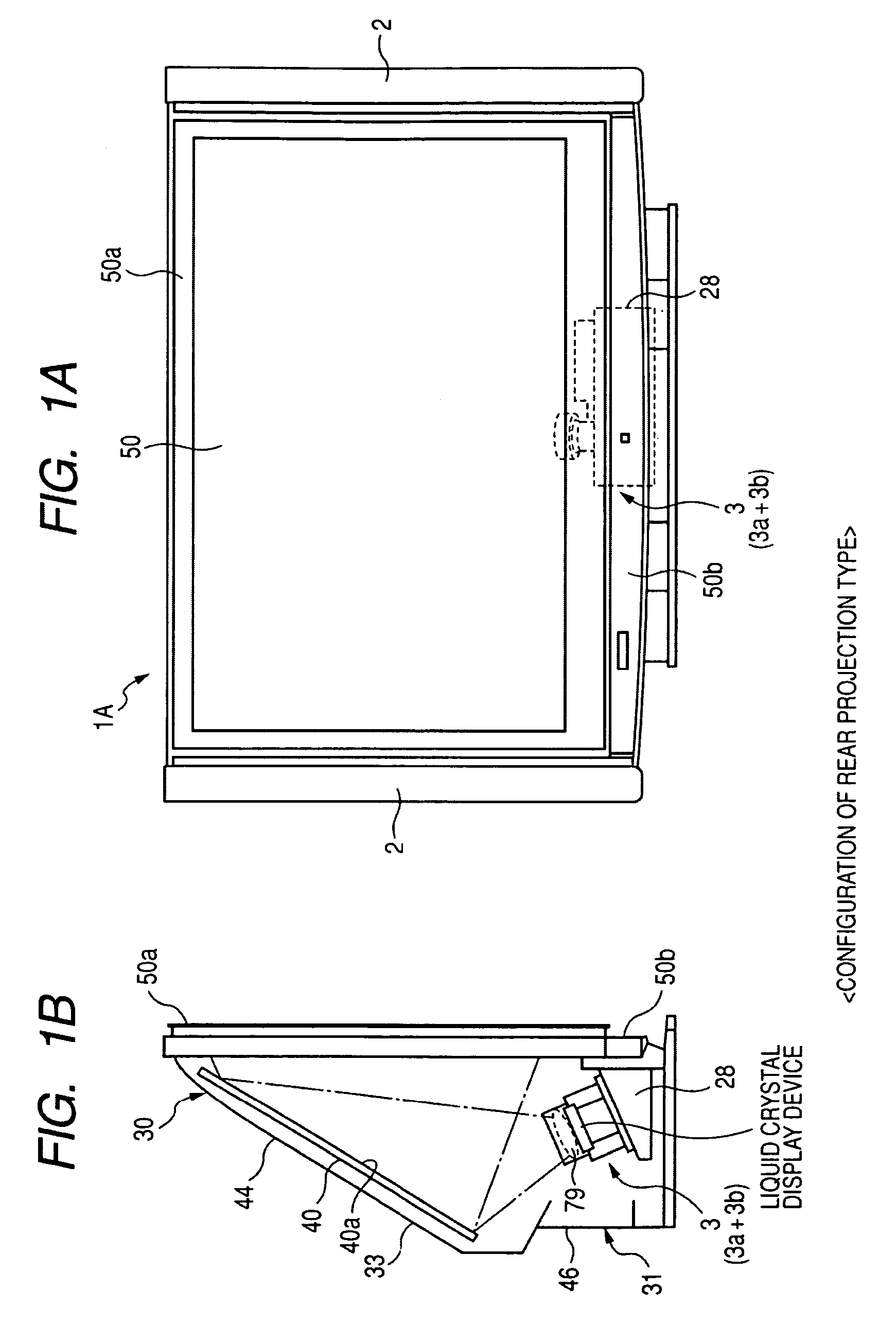
[0076]FIGS. 1A and 1B are diagrams schematically illustrating a projection television as a first example of a rear projection display according to an embodiment of the invention, where FIG. 1A is a front view and FIG. 1B is a side view.

[0077]As shown in FIGS. 1A and 1B, the projection television 1A as the rear projection display includes a frame (a frame of a chassis) 30A and the frame 30A is provided with a projector unit 3 as an example of a projection optical device which is a basic optical system of a projection display, a reflecting mirror 40, and a transmission-type screen 50. A speaker 2 is disposed on both sides of the screen 50. In this example, the frame 30A and the screen 50 constitute the entire chassis. The rear projection display is constructed using the transmission-type screen 50.

[0078]The projector unit 3 serves to output an image-projecting light beam and enlarges and projects an optical image, which is spatially modulated by input...

second example

Projection Display (Second Example)

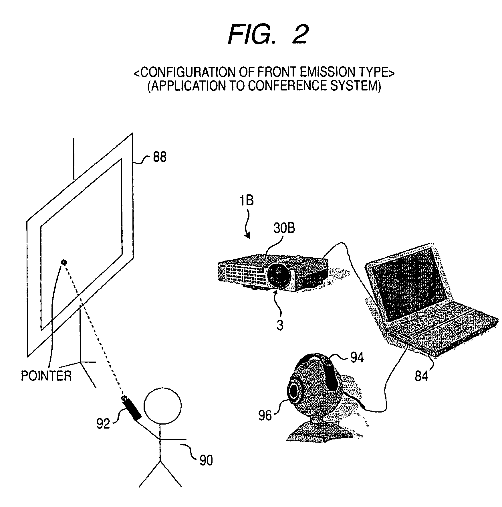
[0089]FIG. 2 is a diagram illustrating the entire configuration of a television conference system as an example of an information providing system employing a second example of the projection display. FIG. 2 shows a configuration of a presenter-side conference room in a usual television conference system. As a structure for displaying image information on a screen, the conference room includes a computer 84 storing a variety of projection image information as conference materials, a liquid crystal projector 1B as a projection device connected to the computer 84, a reflective screen 88 for displaying an image output from the liquid crystal projector 1B, and a laser pointer 92 for displaying a mark as a pointer indicated by the presenter 90 on the information displayed on the screen 88. A front projection display is constructed using the reflective screen 88.

[0090]Similarly to the projection television 1A, a projector unit 3 as an example of the proj...

first embodiment

Modified Example

[0129]FIG. 9 is a diagram illustrating a projector unit 3A_2 (projection optical system) having a modified configuration of the first embodiment using the polarizing beam splitter 100A according to the first embodiment. In this modified configuration, the P polarization component is input to the reflective liquid crystal panel 170 as shown in FIG. 29B. In the device configuration, the known polarizing beam splitter 942 in the configuration shown in FIG. 29B is replaced with the polarizing beam splitter 100A according to the first embodiment. Here, the detailed description thereof is omitted.

[0130]In this modified example, the panel-output beam (S polarization component) spatially modulated on the basis of the image information SV and output from the reflective liquid crystal panel 170 is an optical image corresponding to the image signal SV and is input again to the polarizing beam splitter 100A. At this time, the S polarization component of which the vibration direc...


PUM


Abstract

A polarizing beam splitter includes: first and second prisms each having first and second end surfaces serving as an input surface or an output surface of light and an opposed surface as side surfaces of a pillar-like member; and at least two parallel flat layers disposed in parallel between the opposed surfaces of the first and second prisms. Here, one of the least two parallel flat layers is a first parallel flat layer polarization-separating the input beam. When it is assumed that the refractive index of a base material of the first and second prisms is Np, the resultant refractive index of the parallel flat layers other than the other parallel flat layer of the at least two parallel flat layers is Na, and the refractive index of the other parallel flat layer of the at least two parallel flat layers is Nb, (Na−Np)×(Nb−Np)<0 is satisfied.

Description

CROSS REFERENCES TO RELATED APPLICATIONS[0001]The present invention contains subject matter related to Japanese Patent Application JP 2007-212571 filed in the Japanese Patent Office on Aug. 17, 2007, the entire contents of which is incorporated herein by reference.BACKGROUND OF THE INVENTION[0002]1. Field of the Invention[0003]The present invention relates to an optical prism (a so-called polarizing beam splitter) as an optical member used for a projection optical system for separating polarization by separating an input beam into two linearly-polarized beams perpendicular to each other, transmitting and outputting one polarized beam, and reflecting the other polarized beam, a projection optical device (projection optical system) employing the polarizing beam splitter, and a projection display such as a liquid projector having the projection optical device as a main part or a rear projection display displaying a projected image on a rear projection screen.[0004]2. Description of the...

Claims


Application Information

Patent Timeline
Patent Type & Authority Patents(United States)
IPC IPC(8): G03B21/14G02B5/30G02B27/28
CPCG02B27/283G03B21/28G03B21/208G03B21/2073
Inventor SUNAGA, TOSHIHIRO
Owner SONY CORP
Learn More