
Frame transfer method and device

a frame transfer and frame technology, applied in the field of frame transfer methods and devices, can solve the problems of not being able to perform data with plural bit errors, abnormal operation may sometimes occur in l2 switches, and the like, and achieve the effect of efficient utilization of the address space of a shared buffer

Inactive Publication Date: 2011-11-22
FUJITSU LTD
View PDF6 Cites 0 Cited by
  • Summary
  • Abstract
  • Description
  • Claims
  • Application Information

AI Technical Summary

Benefits of technology

The present invention provides a frame transfer method and device that can efficiently utilize an address space of a shared buffer without a reduction of the address space even if an abnormal operation has occurred in the management of the shared buffer. The method involves storing an address of a shared buffer from which frame data has not been read during one monitor cycle and detecting the address in a next monitor cycle. The detected address is set as a free address of the shared buffer. This allows for the effective utilization of the shared buffer area.

Problems solved by technology

Recently, devices have been micromachined, and an operation speed within a device and an interface speed between devices have been enhanced, so that a malfunction within the device, a noise of the interface between the devices, and the like have become considerable.
Therefore, an abnormal operation may sometimes occur in an L2 switch or the like upon managing a shared buffer.
While such a problem has been approached by correction of data with an error correction code (ECC) or the like, the correction can be performed only to data with a single bit error or the like, but could not be performed to data with plural bit errors.
As to data (addresses of the shared buffer SB) where the error Err has occurred, it is considered that a bit error has occurred.
On the other hand, when an error has occurred, there is a high possibility that the data (address) read upon error occurrence includes a bit error.
Therefore, physically existing 1024 address spaces are reduced to 1022 (−2) address spaces by the error, so that there has been a problem that the capacity of the shared buffer SB becomes smaller every time an error occurs.

Method used


Image

  • Frame transfer method and device
  • Frame transfer method and device
  • Frame transfer method and device

Examples


Embodiment Construction

[1] Arrangement

FIG. 1

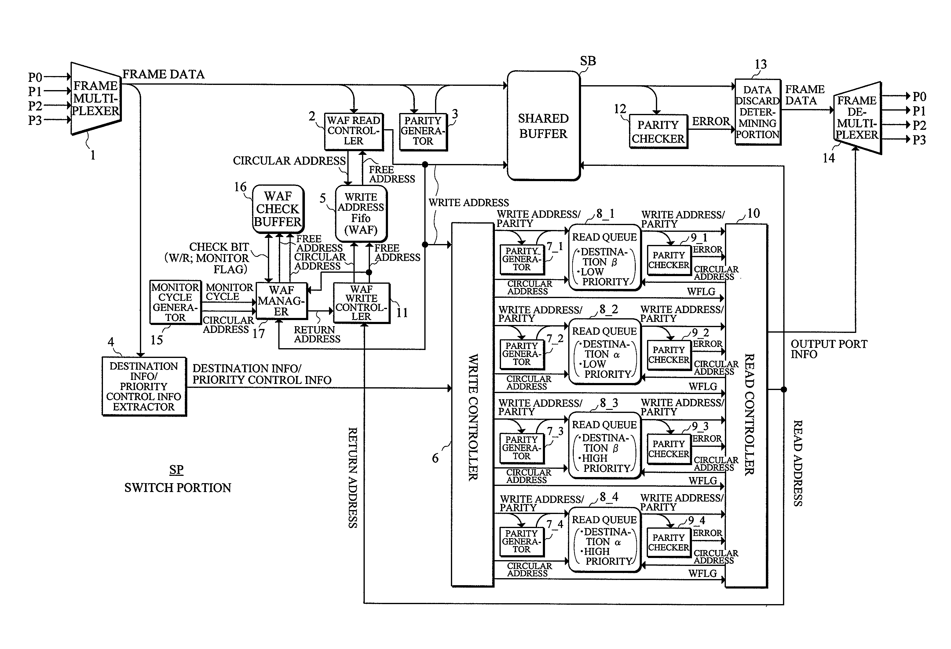
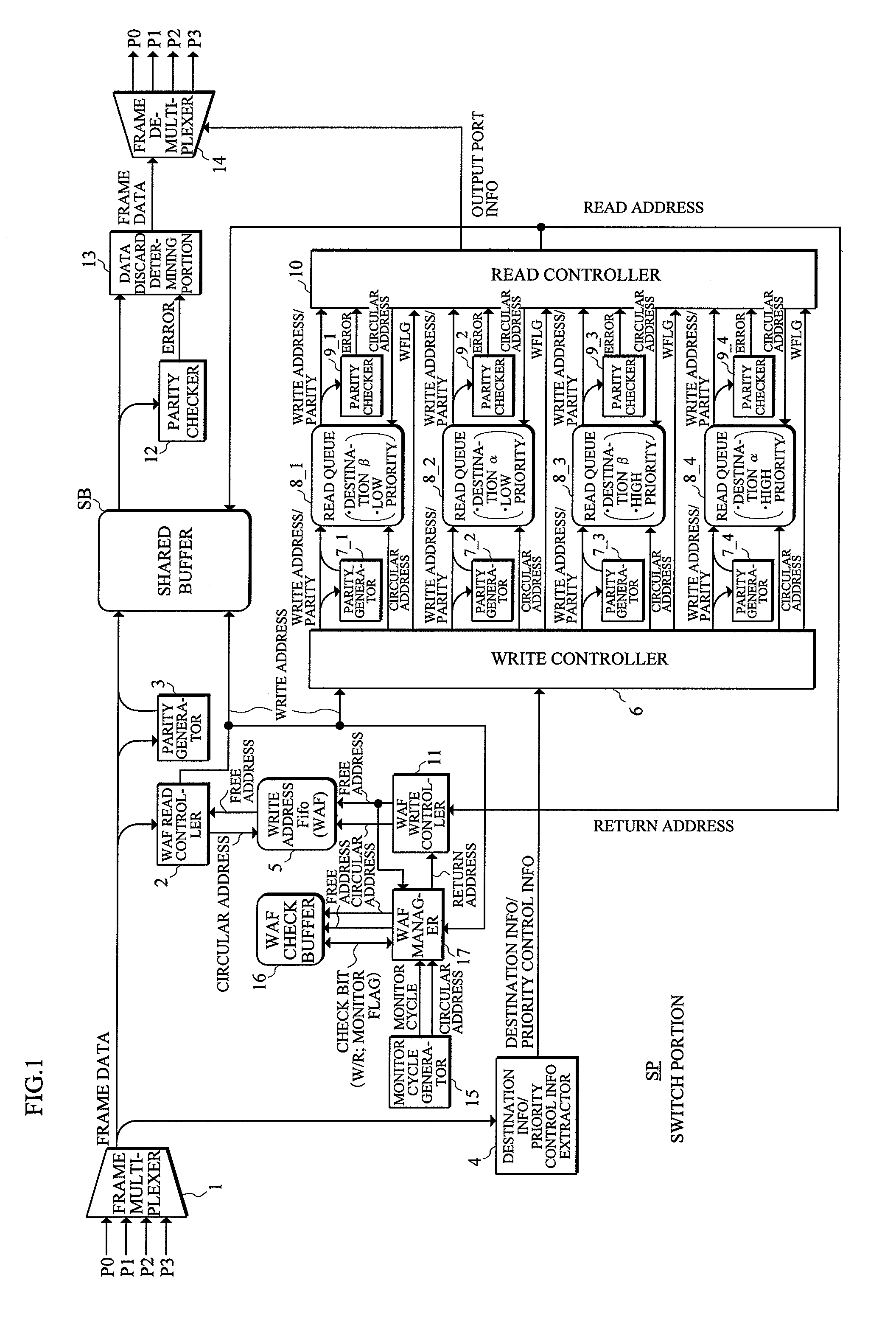
[0070]FIG. 1 shows an arrangement of the present invention applied to the switch card SWC in the general L2 switch shown in FIG. 7. This arrangement further includes a monitor cycle generator 15, a WAF check buffer 16, and a WAF manager 17, in addition to the prior art example shown in FIG. 8.

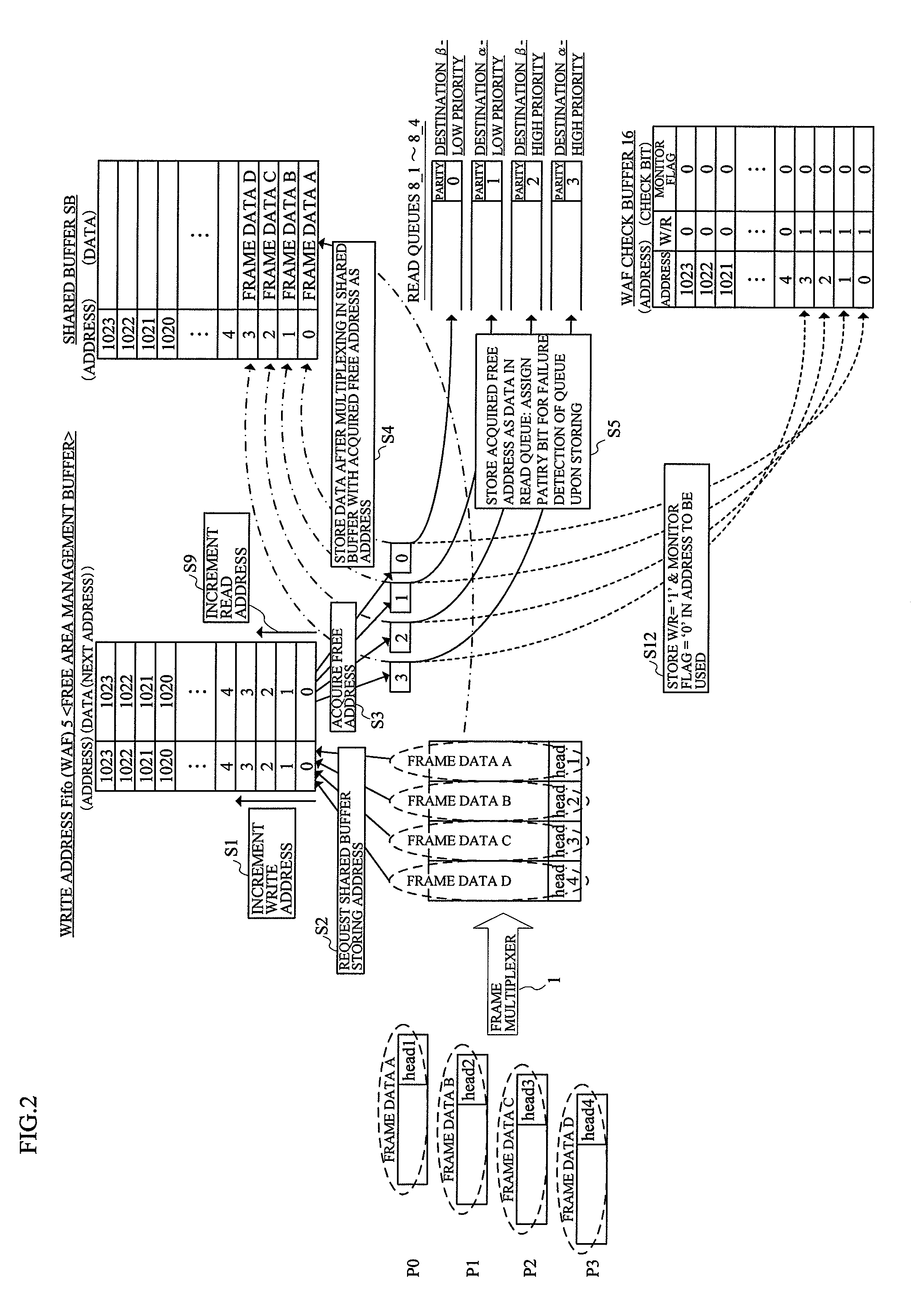
[0071]The WAF manager 17 concurrently receives a free address which the WAF write controller 11 receives from the write controller 10 and writes in the write address Fifo 5 as data, and performs writing check bits (W / R (write / read) state and monitor flag) in the WAF check buffer 16 based on the write address to the shared buffer SB from the WAF read controller 2. When the frame data is read from the shared buffer SB, a W / R state is made “0” (read) and the monitor flag is cleared to “0” (the third state of the check bits).

[0072]The monitor cycle generator 15 generates a monitor cycle (interval in which the frame data written in the shared buffer SB is read without fail), gen...


PUM


Abstract

In a frame transfer method and device by which an address space of a shared buffer can be effectively utilized without a reduction of the space even if an abnormal operation occurs in a management of the shared buffer, after frame data is written in the shared buffer during one monitor cycle when the frame data is to be read without fail from the shared buffer, an address space where the frame data has not been read from the shared buffer is detected during a next monitor cycle, and an address space where not a read but a write of the frame data has been performed at least during the monitor cycle is detected. In the next monitor cycle, the address space is released as a free address of the shared buffer.

Description

BACKGROUND OF THE INVENTION[0001]1. Field of the Invention[0002]The present invention relates to a frame transfer method and device, and in particular to a frame transfer method and device in an L2 switch using a shared buffer.[0003]2. Description of the Related Art[0004]Recently, devices have been micromachined, and an operation speed within a device and an interface speed between devices have been enhanced, so that a malfunction within the device, a noise of the interface between the devices, and the like have become considerable. Therefore, an abnormal operation may sometimes occur in an L2 switch or the like upon managing a shared buffer.[0005]While such a problem has been approached by correction of data with an error correction code (ECC) or the like, the correction can be performed only to data with a single bit error or the like, but could not be performed to data with plural bit errors.[0006]Therefore, when a parity error, an ECC error (uncorrectable error upon detecting pl...

Claims


Application Information

Patent Timeline
Patent Type & Authority Patents(United States)
IPC IPC(8): G06F12/02H04L12/44H04L12/70H04L13/08
CPCH04L49/103H04L49/30H04L49/3009
Inventor KUROSAKI, HIROSHI
Owner FUJITSU LTD
Learn More