Semiconductor device
a technology of semiconductor devices and devices, applied in semiconductor devices, semiconductor/solid-state device details, electrical apparatus, etc., can solve problems such as difficult to achieve such a conventional configuration, complicated interconnect layout, and character degradation, and achieve the effect of higher integration and speed
- Summary
- Abstract
- Description
- Claims
- Application Information
AI Technical Summary
Benefits of technology
Problems solved by technology
Method used
Image
Examples
first embodiment
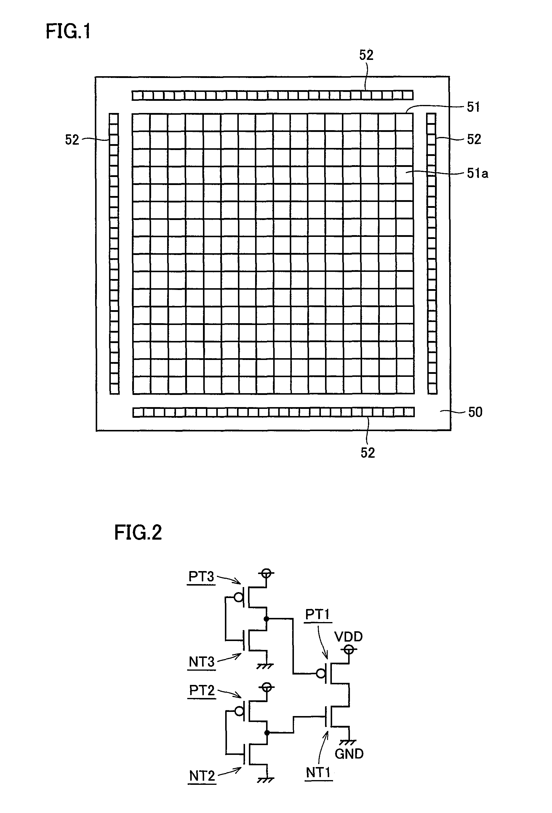
[0042]With reference to FIG. 1, a semiconductor device (e.g., a semiconductor chip) 50 mainly includes on the surface of semiconductor device 50 a standard cell region 51, input / output (I / O) cell regions 52 arranged around standard cell region 51, and pads (not shown) for use in input and output to and from the outside.
[0043]Standard cell region51 has a plurality of standard cells 51a arranged in a matrix. In an SOC using a standard cell library, formed in this standard cell region 51 are a central processing unit (CPU), a random access memory (RAM), a first-in first-out (FIFO), a small computer system interface (SCSI), a sea of gate (SOG), etc.
[0044]With reference to FIG. 2, a circuit of a function element formed in standard cell 51a is, e.g., a partial circuit of a buffer for tri state, and has an output stage and a driver. The output stage is made, e.g., of a CMOS inverter including a pMOS transistor PT1 and an nMOS transistor NT1. The driver is composed, e.g., of a CMOS inverter...
second embodiment
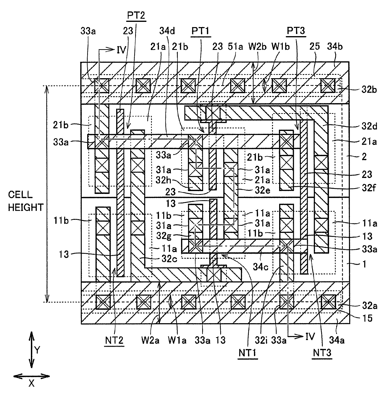
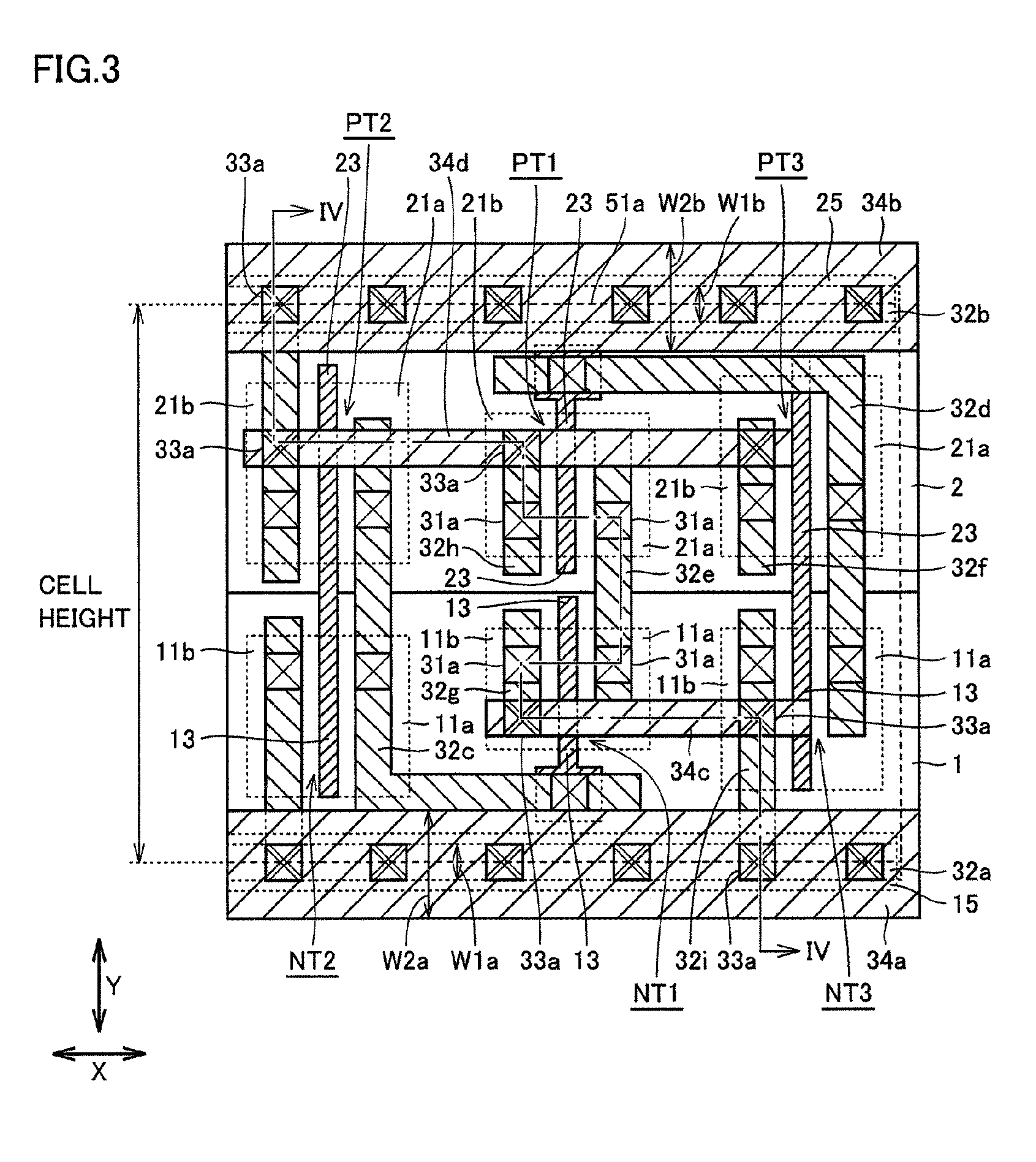
[0084]With reference to FIGS. 5 and 6, in the present embodiment, a configuration will be described in which a CMOS inverter including nMOS transistor NT1 and pMOS transistor PT1 is formed in each of a plurality of standard cells 51a.
[0085]P-type well region 1 is formed on the surface of a semiconductor substrate and n-type well region 2 is selectively formed on the surface in p-type well region 1. Formed on the surface in p-type well region 1 is nMOS transistor NT1. Formed on the surface in n-type well region 2 is pMOS transistor PT1.
[0086]In such a manner as to extend in the lateral direction (X direction in FIG. 5) along one (boundary on the lower side in the Y direction in FIG. 5) of the boundaries in the vertical direction (Y direction in FIG. 5) of standard cell 51a, p+ region 15 is formed on the surface in p-type well region 1. In such a manner as to extend in the lateral direction (X direction in FIG. 5) along the other (boundary on the upper side in the Y direction in FIG....
third embodiment
[0121]The present embodiment realizes the circuit configuration shown in FIG. 2 by modifying the configuration of the second embodiment.
[0122]With reference to FIGS. 9 and 10, in the configuration of the embodiment, for example, nMOS transistor NT1 and pMOS transistor PT1 in the central standard cell 51a, among three aligned standard cells 51a having inverters, correspond to the CMOS inverter of the output stage in FIG. 2.
[0123]A CMOS inverter including nMOS transistor NT2 and pMOS transistor PT2 in right-hand standard cell 51a adjacent to the central standard cell 51a in the drawing and a CMOS inverter including nMOS transistor NT3 and pMOS transistor PT3 of left-hand standard cell 51a adjacent to the central standard cell 51a in the drawing correspond to the driver in FIG. 2.
[0124]Gate electrode layer 13 of nMOS transistor NT1 and gate electrode layer 23 of pMOS transistor PT1 in the central standard cell 51a are electrically separated. An interconnect layer 32e1 in right-hand sta...
PUM
 Abstract
Description
Claims
Application Information
 - R&D
- Intellectual Property
- Life Sciences
- Materials
- Tech Scout
- Unparalleled Data Quality
- Higher Quality Content
- 60% Fewer Hallucinations
Browse by: Latest US Patents, China's latest patents, Technical Efficacy Thesaurus, Application Domain, Technology Topic, Popular Technical Reports.
© 2025 PatSnap. All rights reserved.Legal|Privacy policy|Modern Slavery Act Transparency Statement|Sitemap|About US| Contact US: help@patsnap.com


